Table of Contents
Advertisement
Quick Links
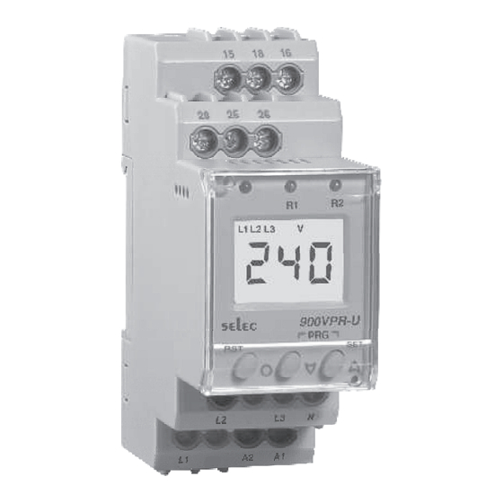
selec
900VPR-U
Operating Instructions
FEATURES
Over voltage, Under voltage, Over frequency,
q
Under frequency, Phase Asymmetry, Phase
failure, Neutral Loss, Phase sequence
monitoring system etc.
True RMS measurement
!
Trip Time delay, Recovery Time delay,
!
Power ON delay
Adjustable switching Hysteresis
!
Two separate alarm relays operation
!
SPECIFICATIONS
DISPLAY
3 Digits, LCD with Backlight
ELECTRICAL CONNECTION
3Ø-3 wire, 3Ø-4 wire
AUXILIARY SUPPLY
85
–
270V AC/DC
50 60Hz
/
OPERATING RANGE
50
–
288
V AC (L- )
N
85
– 00V AC (L- )
5
L
FREQUENCY RANGE
45
–
65Hz
VA RATING
4VA max.
TRIP SETTINGS
Under Voltage
:
50 to 288V AC (L-N)
[for
3Ø-4 wire]
85
to 00V AC ( - )
5
L L
[for
3Ø- wire]
3
Over Voltage
: 50 to 288V AC (L-N)
[for
3Ø- wire]
4
85
to 00V AC ( - )
5
L L
[for
3Ø- wire]
3
Under Frequency : 45 – 65Hz
Over Frequency
: 45 – 65Hz
Phase Asymmetry : 5 – 30%
TIME SETTINGS
Power ON Delay
: 0.5 300sec.
–
Trip Time Delay
: 0 300sec.
–
R
ecovery
Time
: 0 300sec.
–
Response Time
Under Voltage
:
< 120ms
Over Voltage
:
< 120ms
Phase Asymmetry : < 120ms
Phase loss
: < 200ms
Phase sequence < 250ms
:
HYSTERESIS
Voltage
:
1 – 40V
Frequency
:
0. – 2 Hz
1
.0
Asymmetry
:
2
– 20.0%
RESOLUTION
Voltage
: 1V
Frequency
: 0.1Hz
ACCURACY
Voltage
:
±1
%
± 2digits
Frequency
:
±0.5% ± 1digit
Time
:
±
5% of setting 12
±
0ms
(Trip Time Delay, Power ON Delay,
Recovery Time Delay)
OUTPUT SPECIFICATIONS
2 Relays : Relay1 : 1C/O (SPDT)
Relay2 : 1C/O (SPDT)
RELAY RATING
NO (5A, 250V AC)
NC (3A, 250V AC)
LED INDICATION
LED1 : Continuously ON after trip
LED2 : Continuously ON after trip
ENVIRONMENTAL SPECIFICATIONS
- Indoor use
- Altitude of up to 2000 meters
- Pollution degree
II
O
O
Temperature : Operating : - 25 C to +55 C
O
O
Storage
: - 25 C to +70 C
Humidity
: Up to 95% RH, non-condensing
MECHANICAL SPECIFICATIONS
No. of Push Buttons : 3
Size : 35mm width
Mounting : 35mm Din Rail Mount
Wire Size (max) : 4 sq.mm
Screw tightening torque : 0.5 N-M
WEIGHT
150 gms.
SAFETY PRECAUTIONS
All safety related codifications, symbols and
instructions that appear in this operating manual or
on the equipment must be strictly followed to ensure
the safety of the operating personnel as well as the
instrument.
If the equipment is not used in a manner
specified by the manufacturer it might impair the
protection provided by the equipment.
If there is physical damage to the unit then do not
use it.
Read complete instructions prior to installation
and operation of the unit.
WIRING GUIDELINES
WARNING
1. To prevent the risk of electric shock power supply
to the equipment must be kept OFF while doing the
wiring arrangement.
2. Wiring shall be done strictly according to the
terminal layout with shortest connections. Confirm
that all connections are correct.
CAUTION
1. To ensure the safe operation of unit, check the
wiring and connections.
DIMENSIONS ( All dimensions in mm )
35
44
70.50
LED INDICATION CHART
Various Conditions
'R1' LED
'R2' LED
No fault
OFF
R1 Trip
ON
R2 Trip
OFF
Both the Relay Trip
ON
(If Programed for Both Relay)
TERMINAL CONNECTIONS
RELAY 1
15
18
NO1
COM1
RELAY 2
28
25
26
NO2
COM2
NC2
L2
L3
L1
A2
OFF
OFF
ON
ON
Doc. name : OP INST 900VPR-U
16
NC1
N
A1
OP441-V01(Page 1 of 4)
Advertisement
Table of Contents

Subscribe to Our Youtube Channel
Summary of Contents for Selec 900VPR-U
- Page 1 R1 Trip Under Frequency : 45 – 65Hz Over Frequency : 45 – 65Hz R2 Trip Phase Asymmetry : 5 – 30% Both the Relay Trip (If Programed for Both Relay) Doc. name : OP INST 900VPR-U OP441-V01(Page 1 of 4)
- Page 2 Setting Factory set Phase Factory set Yes / No ON / OFF sequence Phase ON / OFF failure Note : Appearance of shaded menus dependant on selection of other parameters Doc. name : OP INST 900VPR-U OP441-V01(Page 2 of 4)
- Page 3 UV protection ON [For 3P4W system] Recovery time 0.0 - 300s Note : Relay 2 (RL2) Default values shown are applicable when Relay 2 (RL2) selected as Relay 1 (RL1) Doc. name : OP INST 900VPR-U OP441-V01(Page 3 of 4)
- Page 4 [For 3P3W system] voltage for Fax No. : +91-22-28471733 I Toll free : 1800 227 353 50 - 288V(Default : 184) Relay 1 Website: www.selec.com Email: sales@selec.com [For 3P4W system] Doc. name : OP INST 900VPR-U OP441-V01(Page 4 of 4)
Need help?
Do you have a question about the 900VPR-U and is the answer not in the manual?
Questions and answers