Advertisement
Quick Start
- Power on your SMAN by holding the ON/OFF button for 1 second.
- Select desired units (English or Metric) by pressing the UNITS button (SMAN3) or holding the ENTER button for 1 second (SMAN2).
- Calibrate temperature and/or pressure as needed. See calibration sections for more details.
- Connect to the system.
- Press the circular button to select your desired function.
Description
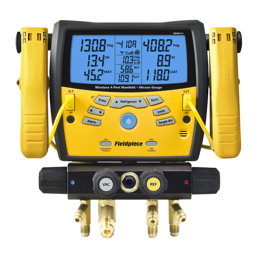
Your SMAN is the state-of-the-art portable digital refrigerant manifold and vacuum gauge (SMAN3) for A/C and refrigeration service. Your SMAN combines high pressure manifold gauges, a superheat/subcooling calculator, micron gauge for vacuum (SMAN3), and temperature measurements into one easy-to-use instrument. Your SMAN calculates and displays target superheat and actual superheat to ensure proper charging of a unit. Use your SMAN as a dual temperature instrument to simultaneously display two temperatures using any K-type thermocouple.
Your SMAN is designed to meet the demands of the HVAC/R technician with a ruggedized rubber boot for durability, a metal hanger for easy storage and a high quality nylon case. A bright blue backlight and very large, easily viewable display lets you see your measurements in any work environment. SMAN has a very intuitive user interface and extremely long battery life.
Your SMAN comes pre-programmed with the most accurate P-T charts for the most common refrigerants in the field so you are always prepared for any job.
Display

Psig Pressure (pounds/in2)
Kpa Pressure (Kilopascals)
inHg Negative Pressure (inches of mercury)
cmHg NegativePressure (cm of mercury)

SH Superheat
T1 T1 Direct
VSAT Vapor Saturation Temperature
IDWB Indoor Wet Bulb

Stable Micron Reading Has Stabilized
Set Set Mode
Alarm Alarm Mode
Hi High Alarm
Lo Low Alarm
Microns Vacuum (Microns of Mercury)
Target SH Target Superheat

Psig Pressure (pounds/in2)
Kpa Pressure (Kilopascals)
inHg Negative Pressure (inches of mercury)
cmHg NegativePressure (cm of mercury)

SC Subcooling
T2 T2 Direct
LSAT Liquid Saturation Temperature
ODDB Outdoor Dry Bulb
 Vacuum Stopwatch
HH:MM:SS Hours: Minutes or Minutes: Seconds

 Battery Life
APO Auto Power Off Enabled
R- Selected Refrigerant of System
Controls

- Insert K-type thermocouple plugs here.
- Temperature calibration pots.
- Press to zero atmospheric pressure.
- Press to linear adjust pressure curve. (See Advanced Pressure Calibration section.)
- Press to engage backlight. Hold when powering on to toggle Auto Power Off.
- Press/hold to cycle through refrigerants.
- Hold 1 second to toggle power on/off.
- Press up or down arrow to adjust values.
- Press to confirm selection. For the SMAN2, hold 1 second to adjust units.
- Hold to enter alarm setup mode. (SMAN3)
- Press to toggle through temperature tests. Hold to auto-toggle.
- Press to adjust units. (SMAN3)
- Turn clockwise to close Low side port.
- Turn clockwise to close High side port.
Functions
Standard Pressure
- Connect your SMAN to the system using EPA approved 1/4in refrigerant hoses.
- Read pressures directly from the upper display.
Superheat and Subcooling
- Press circular button to cycle through temperature modes until SH and SC are shown. While the SMAN can show superheat and subcooling simultaneously, most technicians will only measure one, depending on the system.
- Choose the appropriate refrigerant using the REFRIGERANT button.
- Connect the K-type thermocouple and EPA approved refrigerant hoses to your SMAN.
- Connect your SMAN to the system:
Superheat: Hand tighten low side hose to suction line service port. Place the thermocouple on the suction line between the evaporator and compressor, no closer than 6 inches to compressor.
Subcooling: Hand tighten high side hose to liquid line service port. Place the thermocouple on the liquid line between the condenser and expansion valve (TXV), as close to the service port as possible. - For reliable readings you must let the system run continuously for 15 minutes to stabilize.
- Add or remove refrigerant using the low and high side valves as needed. If adding or removing refrigerant, let the system stabilize again for 15 minutes before reading the measurement.
T1 T2 Direct
- Press circular button until T1 and T2 are shown.
- Plug in any K-type thermocouple into T1 and/or T2.
- Read the temperature directly from the display.
Saturation
Shows vapor (VSAT) and liquid saturation (LSAT) temperatures, based on the pressures measured and the refrigerant selected.
Target Superheat
- Press circular button until Target SH is shown.
- Plug the ATWB1 Wet bulb K-type thermocouple into T1 and ATA1 Dry bulb K-type thermocouple into T2.
- Use the arrow buttons to select which temperature you want to measure fi rst. A blinking value means the SMAN is displaying the real-time temperature.
- For IDWB, wet the sock of the ATWB1. Clip it to the front of the evaporator coil or fi lter. When the wet bulb temperature reaches its lowest point and stabilizes. ENTER locks the reading. "OL" will show if reading outside wet bulb charts. Re-take the measurement.
- For ODDB, clip the ATA1 thermocouple to the side of the condenser. Once reading is stable, press ENTER. "OL" will show if reading outside dry bulb charts. Re-take the measurement. For best results, keep the ATA1 away from direct sunlight.
- Once both IDWB and ODDB are set, the Target Superheat will display in the lower left corner of the display. If the inputted IDWB and ODDB temperatures indicate the Target Superheat is negative, "OL" will display in the lower left corner.
- To change either IDWB or ODDB, press the UP/DOWN arrow button until the label (IDWB or ODDB) you wish to change is blinking. Press ENTER and the value will begin to blink. Re-take the measurement and press ENTER to lock in the new measurement. The newly calculated Target Superheat will be displayed in the lower left corner.
- To clear both IDWB and ODDB at the same time, press the ENTER button. This will only work when a Target Superheat or "OL" is displayed in the lower left corner.
Pulling a Vacuum (model SMAN3)
Follow all manufacturers' evacuation procedures over those in this manual.
 Note: larger systems may take much longer to reach a deep vacuum and a diff erent evacuation method or equipment might be preferred.
- Connect your SMAN3 inline between your vacuum pump and the system, then power on your SMAN3.
- Draw a vacuum on the system. The SMAN will automatically sense the negative pressure and display the vacuum in microns of mercury. Indicators for increasing or decreasing pressure will be shown.
- Press Alarm button to toggle between the High (Hi) alarm, the Low (Lo) alarm and no alarm. (No display for no alarm.) (Note: The stopwatch will start when an alarm is selected. Pressing Alarm will reset the stopwatch.)
- When the rate of change in pressure is zero or near zero, Stable will appear in the lower left corner of the display.
Additional Tips
In order to achieve a deep vacuum as quickly as possible the following practices are suggested.
- Use the shortest hoses with the largest diameter available.
- Remove Schrader cores and core depressors. Core removal tools like the "MegaFlow Valve Core Removal Tool" can be purchased to help with this process.
- Inspect the rubber seals at both ends of your hoses for damage that may result in leakage.
- Do not use hoses with low loss fi ttings when evacuating or pulling a vacuum on a system.
Set Vacuum Alarms (SMAN3)
- Hold the Alarm button for one second to enter Alarm Set mode.
- Press the Alarm button to toggle between Alarm Hi and Lo.
- Use arrow buttons to adjust each alarm value.
- Press ENTER to lock both alarms in.
What is Superheat and Subcooling? Why Do I Need to Measure It?
Superheat is the difference between the actual temperature of the refrigerant (gas) as it leaves the evaporator and the boiling point of the refrigerant. After boiling, the refrigerant continues to heat up. The number of degrees it "heats up" after boiling is called the superheat. Under worst case conditions (low load for fi xed orifi ce systems), the refrigerant in the evaporator boils off near the end of the evaporator coil. To make sure liquid doesn't enter the compressor under the worst case condition (low load), the refrigerator or A/C manufacturers publish charts indicating what the superheat should be at a given indoor wet bulb measurement and outdoor air temperature. Measuring superheat is your best indication on a fixed orifice system of the proper refrigerant charge and operating conditions. If everything else is working properly and the actual superheat is too high, add refrigerant. If it's too low, evacuate refrigerant. Subcooling is the diff erence between the boiling point of the refrigerant in the condenser and the actual temperature of the refrigerant
Measuring superheat is your best indication on a fixed orifice system of the proper refrigerant charge and operating conditions. If everything else is working properly and the actual superheat is too high, add refrigerant. If it's too low, evacuate refrigerant.
Subcooling is the diff erence between the boiling point of the refrigerant in the condenser and the actual temperature of the refrigerant as it leaves the condenser. The degrees that the refrigerant "cools down" below the boiling point is the subcooling. Under worst case scenario (low load for TXV) the subcooling will continue to rise. If the subcooling rises too high, liquid may be backed into the compressor causing damage and catastrophic failure. See www.fieldpiececom for more technical articles.

 Location of Subcooling Test
 Location of Superheat Test
Specifications
Accuracy: Stated accuracy @ 73°F±9°F (23°C±5°C), <75%RH
Temperature coefficient: 0.1 x (specified accuracy) per °C (0°C to 18°C, 28°C to 50°C), per 0.6°F (32°F to 64°F, 82°F to 122°F)
Operating environment: 32°F to 122°F (0°C to 50°C) at <75% relative humidity
Storage temperature: -4°F to 140°F (-20°C to 60°C), 0 to 80% RH (with battery removed)
Display size: 5 inches (diagonal)
Backlight: Blue (On for 1 minute unless turned off manually)
Battery: 6 x AA (Battery life below based on alkaline type)
Battery life (SMAN2): Approx. 500 hours (without backlight)
Battery life (SMAN3): Approx. 135 hours (without backlight)
Low battery indication:  is displayed when the battery voltage drops below the operating level
Auto Shut off: 30 minutes of inactivity when APO is activated
Over range: "OL" or "-OL" is displayed
Weight: 3.05 lbs (1.38 kg)
Pressure
Connector Type: Standard 1/4 NPT male flare fitting
Range: 29" HgV to 500Psig (English), 74 cmHgV to 0 to 4000KPa (Metric)
Resolution: 0.1 psi/inHg; 1 kPa/cmHg
Accuracy: 29" HgV to 0" HgV: ±0.2" HgV
74 cmHgV to 0 cmHgV: ±0.4 cmHgV
0 to 200 Psig: ±1 Psi, 0 to 1378 KPa: ±7 KPa
200 to 500 Psig: ±0.3%+1 Psi, 1378 to 3447KPa: ±0.3%+7 Kpa
Maximum Overload pressure: 800 psig
Units: Psig, kPa, inHg, and cmHg
Microns for Vacuum (SMAN3 only)
Connector Type: Standard 1/4 NPT male flare fitting
Range: 50 to 9999 microns of mercury
Resolution: 1 micron (50 to 2000 microns), 250 microns (2001 to 5000 microns), 500 microns (5001 to 8000 microns), 1000 microns (8001 to 9999 microns)
Accuracy: ±10% or ±10 microns, whichever is greater (50 to 1000 microns)
Maximum Overload pressure: 500 psig
Units: Microns of mercury
Temperature
Sensor type: K-Type thermocouple
Range: -76°F to 999.9°F (-60°C to 537.0°C)
Resolution: 0.1°F/°C
Accuracy: ±(1.0°F) -76°F to 199.9°F; ±(0.5°C) -60°C to 93°C
±(2.0°F) 200°F to 999.9°F; ±(1.0°C) 93°C to 537.0°C
Note: All accuracies are after a field calibration.
Refrigerants
The P-T charts of the following refrigerants come pre-programmed into your SMAN. In numerical order:
R11, R113, R114, R12, R123, R124, R125, R13, R134A, R22, R23, R401A(MP39), R401B, R402A, R402B, R404A, R406A, R407A, R407C, R408A, R409A, R410A, R414B (Hotshot), R416A, R417A, R420A, R421A, R421B, R422A, R422B(NU22B), R422C(Oneshot), R422D, R424A,
R434A(RS-45), R438A(MO99), R500, R502, R503, R507A
Maintenance
Clean the exterior with a dry cloth. Do not use liquid.
Battery Replacement
The battery must be replaced when the battery life indicator  is empty. Turn your SMAN off and replace with 6 AA batteries.
Cleaning the Sensors (SMAN3)
Over time, the vacuum sensor of the SMAN3 may become contaminated with dirt, oil, and other contaminents introduced from pulling vacuums.
- Never use an object such as a cotton swab to clean the sensor, you may cause damage to the sensor.
- Open all knobs/valves, and cap all the ports except for the center port.
- Drop enough Isopropyl (rubbing) alcohol into the uncapped port using an eye dropper or funnel so that it can fl ush out contaminents.
- Cap central port and gently shake your SMAN upside down to clean sensor.
- Turn right side up. Open a port to pour out the rubbing alcohol and open all ports to allow sensors to dry out; usually an hour or so.
Calibration
Temperature
To calibrate your SMAN temperature thermocouples, adjust the pot on the front of the meter labeled T1 Cal or T2 Cal. The best way to calibrate is to match to a known temperature. Ice water is very close to 32°F and is readily available. Accuracies of one degree or better are easily obtained.
- Stabilize a large cup of ice water by stirring. Pure, distilled water will be the most accurate.
- Press the circular button until your SMAN enters Direct Temperature (T1 T2) mode.
- Immerse the temp probe in ice water from T1 and adjust the T1 Cal pot with a fl athead screwdriver and let it stabilize, keep stirring.
- Repeat Step 3 for temp probe in T2.
Pressure
To calibrate your SMAN pressure sensors to atmospheric pressure, ensure that your SMAN is disconnected from any pressure source and at equilibrium with the ambient pressure.
- SMAN must be in Superheat/Subcooling, Saturation, or T1 T2 Direct mode.
- Press the CAL Atmospheric Pressure button and your SMAN will set the zero point of pressure to the ambient pressure.
Advanced Pressure Calibration
Your SMAN has the ability to perform a linear adjustment of the pressure sensors based on refrigerant type, temperature, and pressure.
- Press circular button until your SMAN enters T1 T2 Direct mode.
- Plug in a K-type thermocouple into T1. (A bead type thermocouple is recommended.)
- Connect the SMAN to a refrigerant cylinder of known refrigerant using an EPA approved service hose. Be sure to open both HIGH and LOW side valves on your manifold and cap the unused ports. (If caps are not available you can connect both ends of a refrigerant hose to the two unused caps. Note you will lose some refrigerant into the hose using this method.)
- Press the REFRIGERANT button to match the refrigerant of the cylinder you are using.
- Attach bead-type thermocouple to the side of the cylinder using tape. It is recommended to attach in the middle of the cylinder.
![]()
Let the temperature of the thermocouple stabilize to the refrigerant temperature for 1 to 2 minutes or until stable. - Open the refrigerant cylinder. The pressure inside cylinder should now be displayed on both HIGH and LOW side pressure sensors.
- Press the CAL Test Pressure button.

Your SMAN refers to the built-in P-T charts to compare the temperature of the refrigerant to the vapor saturation temperature. If the pressures on your SMAN are within 3psi of the pressure corresponding to the vapor saturation temperature, your SMAN will linearly adjust the pressure readings to match the P-T chart.
Limited Warranty
This meter is warranted against defects in material or workmanship for one year from date of purchase. Fieldpiece will replace or repair the defective unit, at its option, subject to verifi cation of the defect.
This warranty does not apply to defects resulting from abuse, neglect, accident, unauthorized repair, alteration, or unreasonable use of the instrument.
Any implied warranties arising from the sale of a Fieldpiece product, including but not limited to implied warranties of merchantability and fi tness for a particular purpose, are limited to the above. Fieldpiece shall not be liable for loss of use of the instrument or other incidental or consequential damages, expenses, or economic loss, or for any claim of such damage, expenses, or economic loss.
State laws vary. The above limitations or exclusions may not apply to you.
Safety Information
 WARNINGS
DO NOT APPLY MORE THAN 800 PSI TO ANY PORT ON THE MANIFOLD.
FOLLOW ALL EQUIPMENT MANUFACTURER'S TESTING PROCEDURES ABOVE THOSE IN THIS MANUAL IN REGARDS TO PROPERLY SERVICING THEIR EQUIPMENT.
Obtaining Service
Call Fieldpiece Instruments for one-pricefi x-all warranty service pricing. Send check or money order for the amount quoted. Send your digital manifold, freight prepaid, to Fieldpiece Instruments. Send proof of date and location of purchase for in-warranty service. The meter will be repaired or replaced, at the option of Fieldpiece, and returned via least cost transportation.
© Fieldpiece Instruments, Inc 2010; v16

Documents / Resources
References
Download manual
Here you can download full pdf version of manual, it may contain additional safety instructions, warranty information, FCC rules, etc.
Download Fieldpiece SMAN2, SMAN3 - Digital Manifold & Vacuum Gauge Manual
Advertisement

Need help?
Do you have a question about the SMAN2 and is the answer not in the manual?
Questions and answers