Table of Contents
Advertisement
Advertisement
Table of Contents

Related Manuals for Individual Computers Keyrah v3

Summary of Contents for Individual Computers Keyrah v3
- Page 1 Keyrah v3 User Manual 21/04/23...
-
Page 2: Table Of Contents
Content Content 1. Content.............................2 2. Introduction............................3 3. Using Keyrah V3..........................5 3.1 Keyboards..........................5 3.1.1 Matrix Connectors......................5 3.1.2 Serial Connectors.......................5 3.1.3 PS/2 Connector........................5 3.1.4 DB25 Connector........................5 3.1.5 Locking Keys........................6 3.2 LEDs............................7 3.2.1 Connectors.........................7 3.2.2 Power LED.........................7 3.2.3 Keyboard status LEDs.......................7 3.3 Joystick Ports..........................8 3.4 Power Switch..........................9... -
Page 3: Introduction
Introduction Introduction Thank you for purchasing an individual Computers product. It is important to read the following instructions carefully before attempting installation. Individual Computers cannot be held responsible for any damage caused due to incorrect installation. Before installing Keyrah in the case of a C128, C64, VIC-20 or C-16, please remove the mainboard of the old computer. -
Page 4: Using Keyrah V3
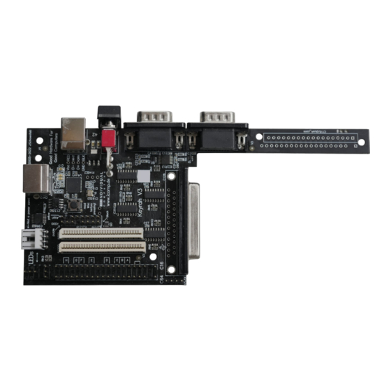
Using Keyrah V3 Using Keyrah V3 3.1 Keyboards 3.1.1 Matrix Connectors Some keyboards can be connected to one of the matrix connectors on the Keyrah v3 board: • (1) VIC20, C64 • (2) C16 • (3) Amiga 1200 • (4) Amiga 600 3.1.2 Serial Connectors... -
Page 5: Db25 Connector
LED. However, on some of the keyboards that can be used with Keyrah V3, the equivalent keys are either actual mechanically locking keys (eg the CBM keyboards have a mechanical shift-lock key) or the keyboard manages the state of the LEDs on its own and there is no way to modify that state (like with PC/XT keyboards). -
Page 6: Leds
Using Keyrah V3 3.2 LEDs 3.2.1 Connectors There are two types of LED connectors (1) The „C64 Style“ 3 Pin LED Connector next to the keyboard connector. The middle Pin is GND, the pin facing the edge of the board is the Power LED, the pin facing away from the edge is the Num Lock LED. -
Page 7: Power Led
Using Keyrah V3 3.2.2 Power LED The Power LED shows one of three states: • Blinking. This means the device is in pre-initializing state. If it stays in this state then a power cycle is needed. • Fading on and off. This means the device has been suspended. It might be possible to wake it up by pressing any key. - Page 8 Using Keyrah V3 3.2.5 Overview Keyboard Keyboard LEDs Scroll-lock LED (1) Num-lock LED (2) Extra LED Amiga 500 Caps / Num - / - Scroll Amiga 1200 Caps Scroll - / - Atari ST Caps - / - - / -...
-
Page 9: Joystick Ports
Using Keyrah V3 3.3 Joystick Ports Each Joystick Port will appear as a separate HID game controller. (1) The connector further from the power switch is “Port 1” (2) The connector next to the power switch is “Port 2” The following devices are currently supported: •... -
Page 10: Power Switch
Using Keyrah V3 3.4 Buttons 3.4.1 Power Switch (1) The Power switch has three functions: 1. Bottom („off“) and middle („on“) position toggles between alternative keymaps (see 3.6 Keyboard Mapping 2. Press and release top momentary switch to trigger a keypress (by default mapped to the key that brings up the menu and/or disables input capturing in the respective supported emulator). - Page 11 Using Keyrah V3 3.4.3 Boot Button (4) The boot button has two functions: • Press the button to “type” the shift-lock ADC value (see Shift-lock threshold) • To enable mass storage mode for updating the firmware or flashing a keymap, press and hold the button at power up, or hold the button for about 5 seconds (see 3.7 Using a custom...
-
Page 12: Jumpers
Using Keyrah V3 3.5 Jumpers 3.5.1 Keymap select (1) The jumper marked EN/DE selects an alternative keymap (see 3.6 Keyboard Mapping). When the Jumper is closed the german keymap is selected, when it is open the english keymap is selected. - Page 13 Using Keyrah V3 The following keyboards can be selected with jumpers on the C16 pin header. Note that the “Manual Keyboard select” jumper (5 – 4) must be set for any jumpers to be detected. Mode Jumper Pins PS/2 Pos H...
-
Page 14: Keyboard Mapping
Using Keyrah V3 3.6 Keyboard Mapping Generally for all keyboards one of four keymaps can be selected. This is done by using the “power” switch and the EN/DE jumper. The “power” switch switches between a “normal” and a “emulator” keymap: •... -
Page 15: Vic20, C64
Using Keyrah V3 3.6.1 VIC20, C64 For switch position "on" (up), an adapted keyboard layout for C64/VIC-20 is chosen that's perfectly suitable for the emulator "VICE" (use “positional” keymap). For switch position "off" (down), the keyboard layout is adapted for use under the Windows operating system. - Page 16 Using Keyrah V3 , / < , and < , and < , and ; , and ; . / > . and > . and > . and : . and : / and ? / and ? - and _...
-
Page 17: Fn Extra Key Layer
Using Keyrah V3 Fn Extra Key Layer When the “power” switch is in “off” (down) position, an extra layer of keys, like on other “reduced” keyboard layouts, can be enabled by pressing the “Fn” key – which in this case is the “run/stop”... - Page 18 Using Keyrah V3 C64 Key Extra Key NP 2 NP 3 NP 0...
-
Page 19: C128
The C128 keyboard is a C64 keyboard (see above) with 26 extra keys. To use the C128 keyboard in VICE, use the Keyrah V3 specific keymap that is provided with VICE – without that a handful keys will not work as expected, in particular the “locking” keys. -
Page 20: C16
Using Keyrah V3 3.6.3 C16 For switch position "on" (up), the layout for C16 keyboards is adapted to the emulator "VICE" (select “positional” keymap). C16 Key US layout DE layout Switch down Switch up Switch down Switch up (normal) (emulator) -
Page 21: Fn Extra Key Layer
Using Keyrah V3 Fn Extra Key Layer When the “power” switch is in “off” (down) position, an extra layer of keys, like on other “reduced” keyboard layouts, can be enabled by pressing the “Fn” key – which in this case is the “run/stop”... - Page 22 Using Keyrah V3 C16 Key Extra Key NP 2 NP 3 NP 0 ´ and ` (DE) F1+shift F2+Shift F3+Shift Help+Shift Help...
-
Page 23: Amiga
Using Keyrah V3 3.6.4 Amiga The emulator keymap was tweaked to be used with the WinUAE emulator. Note that to use the numeric keypad, you must disable keypad joystick emulation. Amiga Key US Layout DE Layout Switch down Switch up (emu) - Page 24 Using Keyrah V3 ; / : Ö Keypad + Keypad 0 . / > . / : Keypad , (comma) - / _ Keypad / + / = ´ / ` page up ] / } + / * page down - / _ ẞ...
-
Page 25: Atari St
Using Keyrah V3 3.6.5 Atari ST The emulator keymap in Atari ST mode was tweaked for use with the STEEM emulator. Note that to use the numeric keypad, you must disable keypad joystick emulation. To make all keys work correctly, you’ll have to set PAUSE for the input capturing mode (instead of the default F11/F12). -
Page 26: Fn Extra Key Layer
Using Keyrah V3 Fn Extra Key Layer When the “power” switch is in “off” (down) position, an extra layer of keys, like on other “reduced” keyboard layouts, can be enabled by pressing the “Fn” key – which in this case is the “left shift”... - Page 27 Using Keyrah V3 Atari ST Key US Layout DE Layout Extra Key NP 1 NP 2 NP 3 NP 0...
- Page 28 Using Keyrah V3 3.6.6 PET (via DE25 Adapter) For switch position "on" (up), the layout for PET keyboards is adapted to the emulator "VICE" (select “positional” keymap). US layout DE layout PET Key Switch down Switch up Switch down Switch up...
- Page 29 Using Keyrah V3 Shift+Cursor U/D Right Left Shift+Right Left Shift+Right Shift+Cursor L/R *1) Shift lock will produce a “CAPS lock” event. However, due to how CBM Keyboards work, the left Shift key is always detected as pressed when shift lock is pressed – because of this Keyrah will always remove “left Shift”...
- Page 30 Using Keyrah V3 Fn Extra Key Layer When the “power” switch is in “off” (down) position, an extra layer of keys, like on other “reduced” keyboard layouts, can be enabled by pressing the “Fn” key – which in this case is the “ESC”...
- Page 31 Using Keyrah V3 PET Key Extra Key NP 2 NP 3 NP 0 NP 7 NP 8 NP 9 NP 4 NP 5 NP 6 NP 1 NP 2 NP 3 NP 0 NP . CLR/HOME...
- Page 32 Using Keyrah V3 3.6.7 CBM2 (via DE25 Adapter) For switch position "on" (up), the layout for CBM2 keyboards is adapted to the emulator "VICE" (select “positional” keymap). US layout DE layout CBM2 Key Switch down Switch up Switch down Switch up...
- Page 33 Using Keyrah V3 KP 00 Delete Delete Shift/Lock (*1) CAPS lock CAPS lock CAPS lock CAPS lock *1) Shift lock will produce a “CAPS lock” event. However, due to how CBM Keyboards work, the Shift key is always detected as pressed when shift lock is pressed – because of this Keyrah will...
- Page 34 Using Keyrah V3 Fn Extra Key Layer When the “power” switch is in “off” (down) position, an extra layer of keys, like on other “reduced” keyboard layouts, can be enabled by pressing the “Fn” key – which in this case is the “00”...
- Page 35 Using Keyrah V3 PET Key Extra Key NP 2 NP 3 NP 0...
-
Page 36: Using A Custom Keymap
Using Keyrah V3 3.7 Using a custom Keymap The builtin default keyboard mapping can be replaced by a custom mapping. This mapping needs to be created in an external tool in .uf2 format and then flashed: Either press and hold the button, then connect Keyrah to USB, or press and hold the button for about 5 seconds. - Page 37 Using Keyrah V3 Finally each Keymap is organized like this: Offset + 0x000 (19 rows * 8 bytes) Keyboard Matrix (rows 0 - 18) + 0x098 (16 bytes) Extra Keys (part of Matrix, 2 extra rows) (rows 19 - 20)
-
Page 38: Keyboard Matrix
Using Keyrah V3 3.7.2 Keyboard Matrix CBM Keyboards C16 C64 C128 0 Delete Return CRSR CRSR SHFT X X X X X X X X X X X X 6 Pound * SHFT R Arrow Up CLR/HOME Arrow CTRL Run/... -
Page 39: Amiga Keyboards
Using Keyrah V3 Amiga Keyboards US Layout 0 Help Left Right Down NP - 1 F10 Enter Delete Backspace NP 0 2 F9 < > Space NP 1 3 F8 NP 4 4 F7 NP 7 5 NP / . >... -
Page 40: Atari Keyboards
Using Keyrah V3 Atari Keyboards US Layout Escape 1 Backspace TAB Return CTRL 5 ‘ Left Shift \ Right Shift 7 ALT Space Caps lock F1 8 F6 Home 9 Arrow Up KP - Arrow Left Arrow Right KP +... -
Page 41: Pc Keyboards
Using Keyrah V3 PC Keyboards US Layout 1 F8 Left Alt Left Shift Left CTRL Space Caps lock Right Shift Enter < Backspace KP 1 KP 4 KP 7 KP 0 9 KP . KP 2 KP 5 KP 6... - Page 42 Using Keyrah V3 PET Keyboards US Layout 2 “ KP 8 CRSR right . > L Shift KP . R Shift KP 3 CRSR down O KP 4 RETURN KP 6 KP 5 7 ‘ KP 7 KP 9 , <...
- Page 43 Using Keyrah V3 CBM2 Keyboards US Layout 0 F1 Shift CTRL 1 F7 Space 2 F6 3 F5 4 F4 5 F3 6 F2 7 F8 , < . > 8 F9 9 F10 ‘ “ 10 Cursor down Arrow left...
-
Page 44: Global Extra Keys
Using Keyrah V3 3.7.3 Global extra Keys Appended to the Keyboard specific keymap there is an additional row containing the mapping for features that are always available: 21 Menu Button Power Key ACPI Sleep Extra Button • Menu Button: this is an extra button that can be connected to the “Menu Button” jumper pad. -
Page 45: Configuration Data
Using Keyrah V3 3.7.4 Configuration Data The last block (before the ID tag) are 32 bytes of configuration data Offset Len Description 0xD0 Left shift row (C16) 0xD1 Left shift column (C16) 0xD2 Right shift row 0xD3 Right shift column... -
Page 46: Appendix
4.1 C116/Plus4 Adapter (1) Like Keyrah V2, Keyrah V3 comes with preparations for building an adapter that will allow you to connect a C116 / Plus4 keyboard. The “tail” of the circuit board can be cut off (be careful, use a sharp knife) and contains the required traces and solder pads for soldering an FPC connector for the keyboard cable, and a female pin header that can be connected to the C16 pin header on Keyrah. -
Page 47: Pinouts
Appendix 4.2 Pinouts 4.2.1 DE9 Connectors The joystick ports are wired the same way as on a C64: Function Down Left Right POT Y Fire +5V (max. 100 mA) POT X For much more elaborate technical information about this port, visit our wiki at http://wiki.icomp.de/wiki/DE-9_Joystick... -
Page 48: Db25 Connector
Appendix 4.2.2 DB25 Connector 13 o 25 o o 14 SX64 Kbd C128D Kbd CBM8296 adapter CBM7x0 adapter ID bridge to pin #22 SR Cascade Restore Restore Column 3 Column 3 Column 7 Column 6 Column 6 Column 6 Column 5 Column 5 Column 5 Column 5... - Page 49 Appendix 4.2.3 C64 and C64 Keyboard Connectors 20 | o 19 | o Jumper Pos H 18 | o 17 | o Jumper Pos G 16 | o Jumper Pos F 15 | o 14 | o Jumper Pos E 13 | o 12 | o 11 | o...
- Page 50 Appendix Row 6 Row 1 Row 3 Manual keyboard select jumper Extra LED (see 3.2.4 Extra LED) (*) Restore Column 3 Row 6 *) This pin was originally only intended for testing the hardware, directly goes to a I/O pin of the CPU, and is completely unprotected.
-
Page 51: Credits
Credits Credits • Jens Schönfeld – Hardware design and production • Tobias Korbmacher – Firmware, Manual • Daniel Falkenberg – Beta testing • Martin Oswald – Beta testing © 2022-2023 by Individual Computers Jens Schönfeld GmbH all rights reserved. -
Page 52: Fine Print
Fine print Fine print The Keyrah V3 is not designed, authorized or warranted to be suitable for use in life-support devices or systems or other critical operations. Inclusion of the product in such applications is understood to be fully at the customer's risk.
Need help?
Do you have a question about the Keyrah v3 and is the answer not in the manual?
Questions and answers