Advertisement
Pro Scale
Advanced Lighting Control System Installation Instructions - TRX-4
®
The Traxxas Pro Scale® Advanced Lighting Control System
for your TRX-4® Sport consists of two major electronic
components: the Pro Scale Lighting Power Module and
the Pro Scale Lighting Distribution Block.
The Lighting Power Module installs on the chassis and
performs as the voltage regulator and power supply
for the lighting system. It also controls various lighting
functions through the two buttons on the face of the
module and communicates with the receiver in the model
via the communication cable or the optional included
MAXX® Link cable.
The Lighting Distribution Block mounts in the body of
the vehicle and is the distribution hub for all the various
wired lights in your Sport body. Its main function is to
direct power and instructions to the brake lights, reverse
lights, turn signals, and high/low beam lighting.
There is only one rugged breakaway wiring connector
between the Lighting Distribution Block and the Lighting
Power Module for reliable lighting performance, plus it
makes it easy to remove the body for vehicle service. The
connector is designed to break away from the vehicle,
without damage, if the body comes off the vehicle in a crash.
There are lighting channels on the Lighting Power Module
which allow the lighting installed on the chassis to be
permanently connected and integrated into the system.
This is helpful to install features such as rock lights, bumper
lights, and other chassis-mounted accessory lighting.
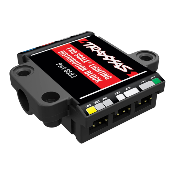
LIGHTING DISTRIBUTION BLOCK
Accessory Connectors
(not used with this kit)
Wiring connectors for the lights are
labeled with letters and/or colors.
A
PRO-SCALE
B
PRO SCALE
®
DISTRIBUTION
DISTRIBUTION BLOCK
C
BLOCK
Part 6593
#XXXX
D
COMMUNICATION CABLES
Your Pro Scale Advanced Lighting Control System includes two communication
cables: the Receiver Communication Cable and the MAXX® Link Cable.
Since your TRX-4 Sport is factory equipped with the TQ receiver, use the Receiver
Communication Cable to connect the Lighting Power Module to the receiver.
The MAXX Link Cable is only for use on models with the TQi radio system.
The 6511 Traxxas Link Wireless Module (sold separately) is required for Traxxas
Link App functionality (only with the MAXX Link Cable). Some models may require
a software update for the TQi receiver via the Traxxas Link App for custom lighting
controls and configurations (see Appendix on page 7 for additional information).
Traxxas, 6250 Traxxas Way, McKinney, TX 75070, Phone: 972-549-3000, Fax: 972-549-3011, e-mail: support@Traxxas.com
HKC21014-R00
Rev 220121
E
F
™
G
LIGHTING
H
K
M
N
CAUTION: RISK OF INJURY!
Use care with hobby knives, tapered reamers, and other cutting tools as they
are extremely sharp and can cause severe injury, deep cuts, and/or punctures.
CAUTION: RISK OF DAMAGE TO BATTERIES!
Always disconnect the battery from the ESC when not in use to prevent the
possibility of over-discharge and battery damage.
Kit Contents:
• Pro Scale Lighting
Power Module
• Power module chassis mount
• Pro Scale Lighting
Distribution Block
• Lighting Distribution
Block mount
• Motor sense wire harness
• Breakaway cable (part of the
Lighting Distribution Block)
• MAXX® Link cable (Data Link)
(TQi Radio System only)
• Receiver communication cable
• Headlights harness assembly
• Tail lights harness assembly
• Turn signal harness
• Reverse lights harness
• Front grille
• Front grille retainer
• Headlight clamps (2)
• Tailgate panel
LIGHTING POWER MODULE
to Traxxas XL-5 HV Electronic
Speed Control (ESC) or direct
battery power source
up to 3s LiPo or 12.6V
Signal Select
(see table in
Operation section)
MAXX® Link Cable Ports
(connects power module to
receiver using MAXX Link cable)
(TQi Radio System only)
(TQi Radio System only)
T R A XXA S .c om
Sport
®
• Tailgate panel retainer
• Tail light clamps (2)
• Reverse light lens, left & right
• Jumper
• LED front bumper light bar
high/low adapter
• LED roof light bar high/low
adapter
• 2.5x8mm button-head screws
(8)
• 2.6x8mm button-head screws
(4)
• 2.5x10mm button-head
screws (2)
• 2.5x10mm countersunk cap
screw (1)
• 2.5x12mm cap screw (1)
• 2.5x18mm cap screw (1)
• Zip ties (10)
• Zip tie mount (3)
• Body templates
TOP VIEW
to Lighting Distribution Block)
PRO SCALE
LIGHTING POWER MODULE
®
Part 6592
MOTOR
MAXX LINK
SENSOR
IN
OUT
RX IN
Receiver Communication Cable Port
(connects power module to receiver
using receiver communication cable)
Motor Sense
Connector Port
SIDE VIEW
MAXX
Link Cable
Receiver Communication
®
Visitez Traxxas.com/manuals pour télécharger
les instructions dans votre langue.
Visite la página Traxxas.com/manuals para
descargar el instrucciones en su idioma.
Auf Traxxas.com/manuals, können Sie
anleitung in Ihrer Sprache downloaden.
Covers Part #8085X
• Double-sided adhesive
foam tape
• Silicone grease
Tools required:
• Safety glasses
• 2.0mm hex wrench
(part #3415, sold separately)
• 1.5mm hex wrench
(part #3415, sold separately)
• Hobby knife
• Small file (optional)
• Tapered body reamer (part
#3433 or #3433X, sold
separately)
• Body scissors (part #3431
(straight tip) or #3132 (curved
tip), sold separately)
• Rotary tool (such as Dremel®)
(optional)
• Wire cutters (to trim zip ties)
• Small needle nose pliers
Breakaway Cable
Connector Port
(connects Power Module
Mode Select
(see table in
Operation section)
Auxiliary Power Connector
(3V - always on)
Cable
1
Advertisement
Table of Contents

Subscribe to Our Youtube Channel
Related Manuals for Traxxas PRO SCALE TRX-4 Sport


Summary of Contents for Traxxas PRO SCALE TRX-4 Sport
- Page 1 MAXX Link Cable Receiver Communication ® a software update for the TQi receiver via the Traxxas Link App for custom lighting Cable (TQi Radio System only) controls and configurations (see Appendix on page 7 for additional information). T R A XXA S .c om Traxxas, 6250 Traxxas Way, McKinney, TX 75070, Phone: 972-549-3000, Fax: 972-549-3011, e-mail: support@Traxxas.com...
-
Page 2: Battery Tray
Note the locations of A. INSTALL THE LIGHTING POWER MODULE ON THE CHASSIS Fig. 5 Fig. 5 Wire Guide Wire Guide any unplugged wires. 1. Install the Power Module mount on the chassis with the included 2.5x10mm Use needle nose countersunk cap screw (Fig. -
Page 3: Chassis Wiring Diagram
High/Low Adapter High/Low Adapter Distribution Block mounted on body Rock Rock Light Light Visit Traxxas.com/ProScaleLighting for additional information about installing and connecting accessories such as auxiliary lighting (rock lights shown, part #8026X, sold separately) to the Pro Scale Lighting Module. - Page 4 E. MODIFY THE BODY Tapered Body Reamer Fig. 12 Diameter Measurements 1. Install the included templates on the body. Align the arrows with the body lines on the front grille and the FRONT 4.5mm 4.5mm tailgate as shown in Fig. 12 and 13. 0.177"...
- Page 5 G. INSTALL THE DISTRIBUTION BLOCK Fig. 14 2.6x8mm BCS 1. Peel the backing from one side of the included adhesive foam tape and attach it to the underside of the Lighting Distribution Block mount as shown in Fig. 14. Do not remove the backing from the other side of the tape yet.
- Page 6 BODY WIRING DIAGRAM Body Wiring (viewed from the underside of the body) Headlight Headlight Turn Signal Turn Signal FRONT Roof Light Bar (if equipped) Breakaway Cable to Lighting Power Module on chassis Rack Scene Rack Scene Light Light (if equipped) (if equipped) Rack Scene Rack Scene...
-
Page 7: Hazard Lights
LIGHTING CONTROL SYSTEM OPERATION HEADLIGHTS MODE SELECTION Selection Action Use the Mode button on the Pro Scale Lighting Power Module to cycle through Low Beam Headlights Default the different lighting modes (from Low Beam Mode to High Beam Mode to High Beam Headlights Press and release Mode Daytime Mode). -
Page 8: Warranty Information
#6511, sold separately) are required. or items that are considered consumable. Traxxas will not pay for the cost of shipping or transportation of a defective component to us. This device complies with FCC Part 15 & IC RSS-210 rules subject...
Need help?
Do you have a question about the PRO SCALE TRX-4 Sport and is the answer not in the manual?
Questions and answers