Table of Contents
Advertisement
Advertisement
Table of Contents

Related Manuals for Shuttle 2000-1

Summary of Contents for Shuttle 2000-1
- Page 1 2000-1 Page 1...
- Page 2 For your safety it is crucial that you read this manual thoroughly and understand the equipment before use. If you have any questions about your Shuttle 2000-1 you can give us a call at +1 (800)-334-5633, email us at customerservice@shuttlesystems.com, or chat with us via live chat at...
-
Page 3: Table Of Contents
IMPORTANT SAFETY INFORMATION …………………………….……………………………………..……. 1 PERSONAL SAFETY ……………………………..….….…………………………………………………..……. 1 SPECIFICATIONS ………………………………………………….…………………………………….…..…… 2 IDENTIFICATION OF THE MANUFACTURER ……………………………………………………..……….…. 3 ASSEMBLY OF THE 2000-1 ……………………………………………………………………….…..………… 4 - ATTACHING STAND-ENDS TO CONNECTOR BAR…………………………………..5 - ATTACHING THE RAILS AND CARRIAGE TO STAND-ENDS………….……………..6 - MOUNTING THE KICKPLATE STRUCTURE……………………………….…………….8 - ATTACHING THE KICKPLATE BOARD………….……………………………………….9... -
Page 4: Important Safety Information
Systems could void the warranty. The 2000-1 is for indoor use only. Do not store the 2000-1 outdoors, near water, or at high humidity levels. Fully assemble the product before using it. Check the product before each use. Do not continue to use the product if it is not working. -
Page 5: Specifications
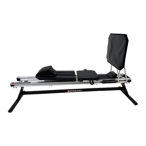
KICKPLATE BACKREST Carriage Capacity: 350 lbs Max Resistance: FOOTREST HEADREST 2000-1: 12-200 lbs* ELASTICORDS Total Elasticords: 2000-1: (8) 12 lb Elasticords SLOTTED PLATE * Elasticords are rated starting resistance, but will gain resistance up to 40% in extension ADJUSTABLE HANDLES... -
Page 6: Identification Of The Manufacturer
TOWERS Carriage Capacity: 350 lbs ADJUSTABLE Max Resistance: PLATE 2000-1: 12-200 lbs* FOOTREST ELASTICORDS Total Elasticords: 2000-1: (8) 12 lb Elasticords SLOTTED PLATE * Elasticords are rated starting resistance, but will gain resistance up to 40% in HANDLEBARS extension BACKREST... -
Page 7: Assembly Of The 2000-1
ASSEMBLY OF THE 2000-1 Assembly of the 2000-1 requires two people. Tools Needed: 7/16 inch socket or combination wrench, 1/2 inch socket of combination wrench. Clinical Plus model will also need a rubber mallet for tower installation. The 2000-1 will come in three boxes:... -
Page 8: Attaching Stand-Ends To Connector Bar
ASSEMBLY OF THE 2000-1 (STEP 1) ATTACHING STAND ENDS TO CONNECTOR BAR STEP 1 ITEMS REQUIRED Stand Ends Connector Bar 1. Position the stand-ends and crossbar on floor with care. Stand ends across from each other with the support bar in- between. -
Page 9: Attaching The Rails And Carriage To Stand-Ends
ASSEMBLY OF THE 2000-1 (STEP 2) ATTACHING 2000-1 RAILS WITH CARRIAGE TO STAND-ENDS STEP 2 ITEMS REQUIRED 2000-1 Rails Carriage Stand-End Assembly 1. Position the carriage and rails so the four bolts fit into the bolt holes on the stand ends. (Pic 2.1) 2. - Page 10 ASSEMBLY OF THE 2000-1 (STEP 2) ATTACHING 2000-1 RAILS WITH CARRIAGE TO STAND-ENDS STEP 2 Page 7...
-
Page 11: Mounting The Kickplate Structure
ASSEMBLY OF THE 2000-1 (STEP 3) MOUNTING THE KICKPLATE STRUCTURE STEP 3 ITEMS REQUIRED Kickplate Structure 1. Release the slider bars with the torque handles. Partially slide the clamp plates out of the head-end of the rails and remove the outer four bolts to make room for the kickplate structure. (Pic 3.1) 2. -
Page 12: Attaching The Kickplate Board
ASSEMBLY OF THE 2000-1 (STEP 4) ATTACHING THE KICKPLATE BOARD STEP 4 ITEMS REQUIRED Kickplate Board 1. Place the kickplate into the kickplate structure with the arrow on the back, pointing up. (Pic 4.1) 2. Attach and secure the kickplate with a 2” washer and torque handle on the lower bolt, and a 2” washer, white plastic spacer, and T-handle on the top bolt. -
Page 13: The Headrest
ASSEMBLY OF THE 2000-1 (STEP 5) THE HEADREST STEP 5 ITEMS REQUIRED Low Profile Headrest 1. Align the velcro strip on the back of the headrest with those on the carriage. Locate the desired position and press down and into place to ensure sufficient contact. (Pic 5.1) -
Page 14: Attaching The Wobble Board (Clinical/Clinical Plus)
ASSEMBLY OF THE 2000-1 (STEP 6) ATTACHING THE WOBBLE BOARD (CLINICAL & CLINICAL PLUS MODELS) STEP 6 ITEMS REQUIRED Wobble Board 1. Attach the hanger to the kickplate board and insert the wobble board into any one of the desired slots. (Pic 6.1, 6.2, 6.3) -
Page 15: Attaching The Towers (Clinical Plus)
Secure the tower crossbar to the 2000-1 rails with the hardware. (Pic 7.2 & 7.3) 3. Loosen the bolts at the bottom of the towers and then place the towers over the black plastic blocks at the stand-ends, making sure the upper eyebolts face the kickplate. - Page 16 ASSEMBLY OF THE 2000-1 (STEP 7) ATTACHING THE TOWERS STEP 7 Page 13...
-
Page 17: Attaching The Pulleys (Clinical Plus)
ASSEMBLY OF THE 2000-1 (STEP 8) ATTACHING THE PULLEYS STEP 8 ITEMS REQUIRED Towers Bag 1. Attach the upper PNF pulleys from the towers bag to the desired height on the towers. 2. Run the end of the rope without handles through the pulleys. Start by feeding the rope through the top pulley and down through the bottom pulley. -
Page 18: Using The Product
USING THE PRODUCT (ALL MODELS) Located inside the 2000-1 carriage are 8 elasticords at the foot-end of the machine with handles. Once the elasticords are attached to the slotted plate at the foot-end of the carriage they engage resistance. Always detach the Elasticords when the machine is not in use. This prevents premature stretching of the Elasticords and greatly extends their life. - Page 19 Warning! Never attempt to adjust the wobble board when the machine is in use. Never attempt to remove or attach the wobble board to the kickplate. 2000-1 WOBBLE Clinical...
- Page 20 The PNF (Proprioceptive Neuromuscular Facilitation) pulley system is designed to allow upper body exercises while laying, sitting, or kneeling on the 2000-1 carriage. It can also be used while standing or sitting next to the 2000-1. The system is designed to be adjusted in the following ways: 1.
-
Page 21: Maintenance And Care
- Loosen and slide the ROM Control (Clinical & Clinical Plus) from both sides of the rails found at the head-end of the machine out of the rails. - Remove the carriage. 2. Lubricate elasticords located under the 2000-1 carriage. - Rub silicone gel into the elasticords. Avoid getting silicone gel on handles. 3. Re-insert carriage into the rail system. -
Page 22: Support
- information about which parts are covered by the warranty and which must be paid for - supply of original spare parts. When you contact Shuttle Technical Support Service you must give the following information: - Product model [A] - Date of purchase... -
Page 23: Warranty
SO THE ABOVE LIMITATIONS MAY NOT APPLY TO YOU. SHUTTLE SYSTEMS shall in no event be liable for death, injuries to persons or property or incidental, contingent, special or consequential damages arising from the use of our products. In administration of this warranty, SHUTTLE SYSTEMS may at its discretion request that the product or part must be returned for examination, postage prepaid, to our Bellingham facility. - Page 24 Scan code to view our 2000-1 Scan code to view our 2000-1 Parts YouTube Playlist...
Need help?
Do you have a question about the 2000-1 and is the answer not in the manual?
Questions and answers