Table of Contents
Advertisement
Quick Links
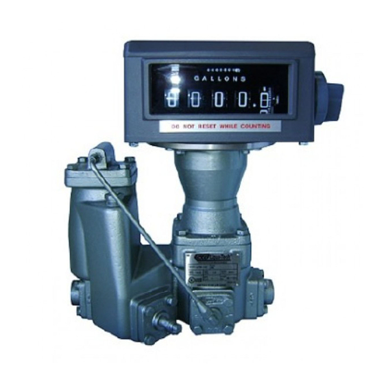
LPM-102
LP-Gas Flowmeter
Operation & Maintenance
TABLE OF CONTENTS
Vent Line
Operation
To Reassemble the Chamber in the
Flowmeter
Trouble Shooting
INTRODUCTION
The Model LPM-102 LP-gas flowmeter is a compact meter consist-
ing of all necessary components required for accurate measure-
ment of liquid propane.
Product entering the flowmeter passes through a strainer assem-
bly, provided to trap particles that could cause premature
inaccuracies in registration.
The LPM102 incorporates a sleeve-type vapor elimination valve
that permits a leak- flow of approximately .02 gpm (75.7 cc)
back to the supply tank. This valve operates in conjunction with
Liqua-Tech s innovative soft seat pressure differential valve. The
valve s piston moves away from its seat when at least 15 psi
(1.034 bar) above product vapor pressure is maintained at the
measuring chamber outlet. This ensures that only liquid is mea-
sured by the meter.
LPM-102 utilizes the proven oscillating piston design. This precise
method of metering has been proven to be both accurate and de-
pendable in thousands of installations. The rotational movement
of the oscillating piston chamber is transferred through a gear
train assembly, which in turn can operate various types of regis-
tration devices.
INSTALLATION
1. Plan the installation for maximum rate of delivery, sizing the
supply tank outlet, piping and valve for free gravity flow to the
pump suction. To accomplish this, locate the pump as close as
possible to the supply tank and use short inlet connections with
few restrictions. Keep the number of elbows to a minimum, and
1
use large radius elbows, wherever possible. To further reduce the
1
likelihood of causing vapor in the pump suction line, a pump by-
1
pass valve should be installed in a return line to the supply tank.
1
2. Locate the flowmeter at any convenient place in the pump dis-
1
charge line. If the flowmeter is to be operated under extremes of
1
environment (dirt, water, physical damage, etc.), an enclosure or
2
other protection should be provided. Allow 6 (15.24 cm) vertical
2
clearance for removal of the register and vapor release mecha-
2
nism. The clearance for removing the differential valve (front on
2
right-hand assembly) is 3½" (8.89 cm). Do not install any bypass
2
around the flowmeter; the valve in such a line might eventually
2
leak, work open, or be left open causing improper measurement.
2
When Installing
2
Secure the connecting piping to prevent strain on the flowmeter
3
casing. Use pipe compound sparingly or suitable pipe tapes on
male threads only. Provide the installation with means for pres-
3
sure relief as outlined in the National Fire Protection Association
Pamphlet 58 or local codes and practices.
3
NOTE: All isolated sections of the system MUST be
3
equipped with a hydrostatic relief device to prevent
3
damage. Failure perform this precaution could result
3
in serious injury or death from explosion/fire.
3
Vent Line
4
The vent line from the flowmeter s vapor vent to the vapor space
4
of the supply tank should be 3/8" (10 mm) minimum inside diam-
eter tube or pipe. A shut-off valve must be installed in the vapor
vent line to permit emptying of the meter for cleaning or when ser-
vice is performed on the flowmeter. The vapor release vent line
must be returned to the supply tank and must not be made a
common connection with other vapor return lines or pump bypass
lines. When properly installed, this line must permit free flow in ei-
ther direction. If valve in vent line is closed, flowmeter will not
function. These instructions must be followed in order to maintain
proper function of the differential valve.
NOTE: A vapor return line should not be used from
supply tank to tank being filled, inasmuch as such
connection would cause confusion as to the amount
delivered as a result of possible passage of vapor in either
direction.
OPERATION
Pressurize the system slowly by allowing vapor to flow through the
vent line. Then pass sufficient liquid through the system to clear
the lines of air and vapor.
After starting the pump, slowly open outlet valve downstream of
the flowmeter. Check the rate of flow after the system is filled; it
should not exceed maximum indicated rate of flow18 gpm (68
lpm).
Adjust the external pump bypass to deliver the maximum practical
rate of flow for the least amount of pump pressure (see pump
manufacturer s instructions).
Maximum working pressure on the system must not exceed 350
psi (24.13 bar). Avoid the use of small diameter hose and exces-
1
Rev. 4/18
Advertisement
Table of Contents

Related Manuals for Liqua-Tech LPM-102

Summary of Contents for Liqua-Tech LPM-102
- Page 1 The vapor release vent line must be returned to the supply tank and must not be made a The Model LPM-102 LP-gas flowmeter is a compact meter consist- common connection with other vapor return lines or pump bypass ing of all necessary components required for accurate measure- ment of liquid propane.
- Page 2 3. Note the numbers stamped on the register change gear (on sive pressures to achieve the desired flow rates; these may result register spindle marked R on the adapter plate) and on the stuff- in leakage and undue wear on the pump. ing box change gear (or flowmeter spindle marked S on the Although all flowmeters are carefully calibrated and tested after adapter plate).
- Page 3 2. Remove the star driver. slots provided and prying it off. Be careful not to scratch or nick 3. Remove the flowmeter main case cover, with gear train assem- any part of the chamber. bly attached. Be careful to keep dirt out of flowmeter and avoid 5.
- Page 4 Vent line from the vapor release valve plugged causing vapor to pass through the flowmeter Consistent over- or Flowmeter in need of calibration under-registration Rev. 4/18 Liqua-Tech Corporation 3501 N. State Street, Ukiah, CA 95482 8 00/659-3556, FAX 707/462-3576 www.liqua-tech.com ltc@liqua-tech.com...
Need help?
Do you have a question about the LPM-102 and is the answer not in the manual?
Questions and answers