Table of Contents
Advertisement
Quick Links
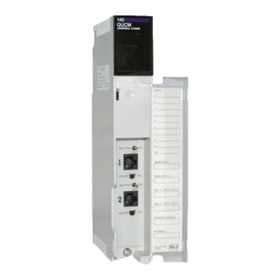
QUCM Limitorque Valve Controller Application Manual
QUCM Limitorque Controller
Installation and Programming Manual
This Manual describes the QUCM application for interfacing Limitorque Valve Actuators to a Modicon Quantum
PLC system.
Effective: 18 March, 2008
Niobrara Research & Development Corporation
P.O. Box 3418 Joplin, MO 64803 USA
Telephone: (800) 235-6723 or (417) 624-8918
Facsimile: (417) 624-8920
www.niobrara.com
Advertisement
Table of Contents

Summary of Contents for Niobrara QUCM
- Page 1 QUCM Limitorque Valve Controller Application Manual QUCM Limitorque Controller Installation and Programming Manual This Manual describes the QUCM application for interfacing Limitorque Valve Actuators to a Modicon Quantum PLC system. Effective: 18 March, 2008 Niobrara Research & Development Corporation P.O. Box 3418 Joplin, MO 64803 USA...
- Page 2 Modicon and Quantum are trademarks of Schneider Electric. Limitorque is a trademark of Limitorque. Subject to change without notice. © Niobrara Research & Development Corporation 2007-2008. All Rights Reserved.
-
Page 3: Table Of Contents
DDC2I DIP Switch Settings ..................8 Valve Configuration and Wiring ................8 Port 1 to the Personal Computer ................9 Loading the Applications into the QUCM ..............9 FWLOAD QUCM Firmware Update..............10 QLOAD Application 1 ..................10 PLC Configuration ....................... 11 PLC Local Rack Setup .................. - Page 4 Figure 2-2 DDC2I to "A2" port RS-485 2-wire cable ..............8 Figure 2-3 PC Connection to QUCM-O serial port ................ 9 Figure 2-4 QUCM-O to RS-232 PC Port (9-pin) (MM1 Cable) ..........9 Figure 2-5 FWLOAD of QUCM Firmware ................. 10 Figure 2-6 QLOAD of Application 1 ...................
-
Page 5: Introduction
Limitorque valve actuators. Both serial ports of the QUCM- OE are connected to a closed ring of actuators and the QUCM can determine if the ring is complete and which valves are accessible from either port of the QUCM. This ring network topology allows for the breaking of the network in one location and still providing control of all of the actuators. -
Page 7: Installation
Installation QUCM Installation Mount the QUCM in an available slot in the register rack. Secure the screw at the bottom of the module. Serial Connections to the QUCM-OE Port 1 to DDC2I to Valves The serial port of the QUCM-OE must be switched to RS-232. The Niobrara cable MM0 is used to connect to the DDC2I. -
Page 8: Ddc2I Dip Switch Settings
Refer to the appropriate Limitorque document for proper actuator configuration and wiring diagrams. Valve 1 Valve 2 Valve 3 QUCM DDC2I Niobrara Fault Active Ready MM0 Cable Valve 6 Valve 5 Valve 4 DDC2I Typical RS-485 wiring system setup 8 Installation QUCM Limitorque Valve Controller Application Manual... -
Page 9: Port 1 To The Personal Computer
Port 1 to the Personal Computer A physical connection must be made from the personal computer to the QUCM in or- der load the QUCM application program. This link may be a serial connection from a COM port on the personal computer to the RS-232 port on the QUCM-OE. The Niobrara MM1 cable may be used for this connection. -
Page 10: Fwload Qucm Firmware Update
Only the 3 light should be on. (The Link and RX E-net lights may be on if the E-net port is connected and there is traffic.) Connect the PC to QUCM Port 1 with a MM1 cable.. Make sure that Port 1 is set to RS-232 mode with the slide switch below the port. -
Page 11: Plc Configuration
If the QUCM is to be used in the local PLC rack with the I/O Scanner setup then make sure that the switch 2 is set to HALT. If the QUCM is to be used in a re- mote or local rack as I/O then set switch 2 to MEM PROT. -
Page 12: Table 2-2 Qucm Status Bit Descriptions
Port 2’s bits including: the most recent valve polled, status of the QUCM, the scan time of the Primary Port in ms, and the scan time of the Secondary Port in ms. The bit-map of the QUCM Status register is shown in Table 2-2. - Page 13 Read Length - This is the number of words read from the valve. This value is normally 7. The QUCM looks at the Read Ref Slave and if it is 400007 and the Read Length is 2 then the QUCM actually reads a block of registers from 7 to 15 but only reports the data from 7 and 15 to the PLC.
-
Page 14: Plc Remote Rack Setup
400001 PLC Remote Rack Setup The QUCM is controlled by 32 4x outputs from the PLC and provides 32 3x inputs to the PLC as shown in Table 2-5. 4x0001 - This is the bitmap of the 14 possible slaves to poll. It is in 984 style where bit 1 is the msb of the word. -
Page 15: Table 2-4 Valve Commands
Stop Network ESD 19200-19300 Move-To % Open position (19200=0%Closed, 19300=100% Open) 4x0019 through 4x0032 - These are the slave addresses for the 14 possible valves to poll. The valid range is 1-250. QUCM Limitorque Valve Controller Application Manual 2 Installation 15... -
Page 16: Table 2-5 I/O Register Map
Consult the QUCM user manual for the meaning of the halt code. Bit 16 is cleared and Bit 15 is set when the QUCM is booted to indicate to the PLC that the QUCM is not allowing writes to the valves. -
Page 17: Table 2-6 Valve Register 9 Bitmap
16. Writes are enabled by the QUCM when both QUCM bit 16 and PLC bit 16 are both set ON. 3x0002 - This register normally shows the slave being polled and it will cycle quickly between 1 and 14. If 3x0001 shows a halt code then this register will show the QUCM source code line number for the halt. -
Page 19: Operation
I/O Scanner (Option Mode) operation is used when the QUCM is located in the PLC rack and switch 2 is set to HALT. I/O Mode is used when the QUCM is located in a Remote Rack and the card is treated as a QUCM I/O card with 32 words in and out. -
Page 20: Incomplete Ring
I/O Scanner Operation The QUCM switch 2 is set to HALT and its slot in the PLC is configured as an NOE- 771-01. The I/O Scanner table in the PLC is used to configure the QUCM for its IP Address, serial port settings, and list of valves to poll. -
Page 21: Example 1 - I/O Scanner
Scanner Entry 1 (serial port setup) is ignored by the QUCM. Example 1 - I/O Scanner Figure 4-1 shows a QUCM in the Processor Rack slot 5 with a ring of 6 valves. Each valve is set for slave address 11 through 16 and is configured for 19200 baud, NONE parity. -
Page 22: Table 4-2 I/O Scanner Example
QUCM port 1. Table 4-5 shows the Health Status when the cable between slaves 13 and 14 is cut leaving slaves 11, 12, and 13 on QUCM port 1 and slaves 14, 15, and 16 on QUCM Port 2. -
Page 23: Table 4-4 Health Registers With All Devices Online
Port 2 - Entries 113-128 0000 0000 0000 0000 0000 300139 Most Recently Polled Entry 0003 300140 QUCM Status 0001 300141 Primary Port Scan Time 028E 300142 Secondary Port Scan Time 0029 QUCM Limitorque Valve Controller Application Manual Operation 23... -
Page 24: Remote Rack I/O Operation
0029 Remote Rack I/O Operation Switch 2 on the QUCM in MEM PROT sets the application to I/O backplane mode for operation in a Quantum Remote Rack. The PLC traffic cop must be configured for QUCM operation with 32 words in and 32 words out. The serial polling operation in I/O mode is the same as I/O Scanner mode. -
Page 25: Figure 4-2 Example 1 With Qucm In Remote Rack
Valve 6 Valve 5 Valve 4 DDC2I Figure 4-2 Example 1 with QUCM in Remote Rack Table 4-6 shows the PLC register data for an online system with some valves open and closed. QUCM Limitorque Valve Controller Application Manual Operation 25... -
Page 26: Table 4-6 Example 2 I/O Register Map With All Slaves Online
Not Used 40128 Not Used 30128 Not Used 40129 Not Used 30129 Not Used 40130 Not Used 30130 Not Used 40131 Not Used 30131 Not Used 40132 Not Used 30132 Not Used 26 Operation QUCM Limitorque Valve Controller Application Manual... -
Page 27: Troubleshooting
There are 10 numberd LEDs at the top of the QUCM which are used to give diagnos- tic information concerning this application. • LED 1 - Port 1 Primary - This light is on when QUCM port 1 is the primary poll- ing port with port 2 acting as the secondary port. -
Page 28: Web Server
• LED 10 - QUCM in Option Mode - Switch 2 must be in Halt for this light to be on. It indicates that the QUCM is emulating an NOE-771-01 and the QUCM must be in the local PLC rack its configuration comes from the I/O Scanner Config Ex- tension for its slot.
Need help?
Do you have a question about the QUCM and is the answer not in the manual?
Questions and answers