
Related Manuals for Ekinex EK-FE1-TP


Summary of Contents for Ekinex EK-FE1-TP
- Page 1 Application manual KNX binary output module EK-FE1-TP 4/8-channel EK-FF1-TP 8/16-channel...
-
Page 2: Table Of Contents
Application manual KNX binary output modules EK-FE1-TP / EK-FF1-TP Contents Scope of the document ..........................5 Product description ............................ 6 Switching, display and connection elements ..................... 7 Configuration ............................. 8 Commissioning ............................8 Function description ........................... 9 Startup ..............................9 Offline operation ............................ - Page 3 Application manual KNX binary output modules EK-FE1-TP / EK-FF1-TP 6.5.2.2 Staircase lighting function ...................... 42 6.5.2.3 Locking function ........................43 6.5.2.4 Logic function ......................... 44 6.5.2.5 Scenes function........................45 6.5.2.6 Watts / Hours counter ......................46 6.5.3 Coupled outputs: Channel x configuration .................. 46 6.5.3.1 Main parameters ........................
- Page 4 Application manual KNX binary output modules EK-FE1-TP / EK-FF1-TP Release Update Date Page 33: corrected the meteo alarms behavior when more than one alarms becomes active, as noticed by Tapko. 15/10/2018 Page 36: regarding the CO 155, the statement “Issued on absolute position movement commands”...
-
Page 5: Scope Of The Document
KNX binary output modules EK-FE1-TP / EK-FF1-TP 1 Scope of the document ® This application manual describes application details for the 2.0 release of the ekinex KNX binary output modules EK-FE1-TP (4/8 channels) and EK-FF1-TP (8/16 channels). The document is aimed at the system configurator as a description and reference of device features and application programming. -
Page 6: Product Description
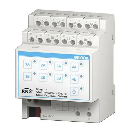
2 Product description ® The ekinex binary output modules EK-FE1-TP and EK-FF1-TP are S-mode KNX modular devices for independent switching respectively of 8 or 16 electrical loads; to this purpose, the outputs of the devices are equipped with potential-free relay contacts. -
Page 7: Switching, Display And Connection Elements
Application manual KNX binary output modules EK-FE1-TP / EK-FF1-TP 3 Switching, display and connection elements The device is equipped with: Membrane keys for manual operation A membrane key to switch between manual and online mode LED indicators for the status of the outputs and for the indication of manual mode ... -
Page 8: Configuration
The exact functionality of the device depends on the software settings. ® In order to configure and commission the device you need ETS4 or later releases and the proper ekinex application program, either APEKFE1TP.knxprod or APEKFF1TP.knxprod, which can be downloaded from ®... -
Page 9: Function Description
Application manual KNX binary output modules EK-FE1-TP / EK-FF1-TP 6 Function description The device is a switching endpoint, which activates its switch channels according to telegrams sent by other devices on the bus. It also incorporates additional features such as e.g. timing and logic combination features, described in the following chapters. -
Page 10: Manual Operation
Application manual KNX binary output modules EK-FE1-TP / EK-FF1-TP Bus on, i.e. after recovery from a KNX bus failure Download of a new or updated configuration from ETS Further events are associated with specific functions such as the Lock or the Forcing functions. -
Page 11: Activation Of Manual Mode
Application manual KNX binary output modules EK-FE1-TP / EK-FF1-TP 6.3.2 Activation of manual mode To switch the device to manual operations mode, proceed as follows: 1) Press the manual mode pushbutton. In normal operation the LED is turned off. When the LED turns on, the whole membrane keypad is activated and the manual operations are allowed. -
Page 12: Online Operation
Application manual KNX binary output modules EK-FE1-TP / EK-FF1-TP 6.4 Online operation All features described below assume the device has been correspondingly programmed by means of the ETS tool. A fully unprogrammed device causes no activity on the bus; it can be switched to manual mode and operated through the membrane keys on the front panel. -
Page 13: Output Features In Independent Mode
Application manual KNX binary output modules EK-FE1-TP / EK-FF1-TP 6.4.4 Output features in independent mode In the most simple case there is only one communication object per channel, “On-Off command”, that switches each channel output directly with a message. By setting the device parameters, it is possible to activate additional features, most of which will also affect the outputs. -
Page 14: Relay Inversion
Application manual KNX binary output modules EK-FE1-TP / EK-FF1-TP It must be noted that, as can be seen from the above diagram, the different features of the output channel can be activated and operated in parallel at the same time; the configurator has the responsibility of taking care that any interference between different functions does not produce unintended effects on the way device outputs are managed. -
Page 15: Staircase Function
Application manual KNX binary output modules EK-FE1-TP / EK-FF1-TP 6.4.4.4 Staircase function This function is intended to provide a simple and flexible way to manage the switching of staircase lights. These have following peculiar requirements: The light is activated by a “start” command (e.g. through a pushbutton or a presence sensor), and normally remain lit for a programmed time duration;... - Page 16 Application manual KNX binary output modules EK-FE1-TP / EK-FF1-TP Following pictures show the Manual Off feature: Fig. 4 - Manual Off feature Release 2.1 - Update: 10/2018 MAEKFE1FF1TP_EN © EKINEX S.p.A. - All rights reserved Page 16...
- Page 17 Application manual KNX binary output modules EK-FE1-TP / EK-FF1-TP Following pictures show the Retrigger feature: Fig. 5 - Retrigger feature Release 2.1 - Update: 10/2018 MAEKFE1FF1TP_EN © EKINEX S.p.A. - All rights reserved Page 17...
- Page 18 Application manual KNX binary output modules EK-FE1-TP / EK-FF1-TP Following pictures show the Pre-warning feature: Fig. 6 - Pre-warning feature Release 2.1 - Update: 10/2018 MAEKFE1FF1TP_EN © EKINEX S.p.A. - All rights reserved Page 18...
-
Page 19: Logic Function
Application manual KNX binary output modules EK-FE1-TP / EK-FF1-TP 6.4.4.5 Logic function The device has a limited provision for the logic processing of internal variables in order to condition the status of outputs. A given incoming output command can be used as an input to a logic block which operation is selectable between OR, AND and XOR (exclusive OR). - Page 20 Application manual KNX binary output modules EK-FE1-TP / EK-FF1-TP This structure allows to implement fairly complex logical combinations; a more generic and powerful programming capability would add more complexity and therefore it would be far beyond the scope of an output module that is simple to use.
- Page 21 Application manual KNX binary output modules EK-FE1-TP / EK-FF1-TP Fig. 10 - Logic XOR function Release 2.1 - Update: 10/2018 MAEKFE1FF1TP_EN © EKINEX S.p.A. - All rights reserved Page 21...
-
Page 22: Lock Function
Application manual KNX binary output modules EK-FE1-TP / EK-FF1-TP 6.4.4.6 Lock function If the locking feature is enabled, the operation of a channel can be inhibited by writing a value in a communication object. The value written is of the KNX type “enable”; please beware that the meaning of this value is “activate lock”, which is not to be confused either with “enable locking function”... -
Page 23: Forcing Function
Application manual KNX binary output modules EK-FE1-TP / EK-FF1-TP 6.4.4.7 Forcing function The forced control is very similar to the basic direct command of the output value, but with the peculiarity that it overrides both the “regular” set value and every other value conditioning feature (i.e. logic function, staircase timing etc.). -
Page 24: Scene Management
Application manual KNX binary output modules EK-FE1-TP / EK-FF1-TP 6.4.4.8 Scene management Each output can be linked to up to 8 scene codes; when one of these scene codes is recalled through a bus command originated by any controller device, the output will assume a preset value. An additional delay can be defined for the output activation (or deactivation) from the moment the scene code is recalled. -
Page 25: Operating Hours / Energy Consumption Counter
Application manual KNX binary output modules EK-FE1-TP / EK-FF1-TP 6.4.4.9 Operating hours / Energy consumption counter For each output, an activation counter can be associated which accumulates the count of hours that the output passed in the “on” state. In terms of communication objects, this counter has the format of a KNX hour counter, thus it also has a “reset”... - Page 26 Application manual KNX binary output modules EK-FE1-TP / EK-FF1-TP “no change” refers to before the event itself (e.g. for the “bus on” event, an output which was “off” before bus recovery will remain “off” thereafter); “previous state” refers to before the condition that is terminated by the event (e.g. for the “bus on”...
-
Page 27: Output Features In Coupled Mode
Application manual KNX binary output modules EK-FE1-TP / EK-FF1-TP 6.4.5 Output features in coupled mode In coupled mode, output pairs can be used to drive three categories of devices: these are grouped under the denomination of Valve actuators (2- or 3-way), Shutters and Venetian Blinds. -
Page 28: Coupled Output Control Basics
Application manual KNX binary output modules EK-FE1-TP / EK-FF1-TP 6.4.5.1 Coupled output control basics The control with coupled outputs is based on three main telegrams, all of which are 1-bit values and thus can convey up to two commands each:... -
Page 29: Valve Control
Application manual KNX binary output modules EK-FE1-TP / EK-FF1-TP 6.4.5.2 Valve control The valve control is the most basic of the three controls available; the control can be configured for both 2- and 3-way actuators. A 2-way actuator has two command lines: one line brings the valve in one (say “open”) position, while the other moves it the opposite way. -
Page 30: Venetian Blind Control
Application manual KNX binary output modules EK-FE1-TP / EK-FF1-TP Fig. 17 - Dimmer-type blind control As already mentioned, the full-scale movement time value must be set; there are two parameters for this purpose, one for the upward and one for the downward direction. Times in two directions may be different for mechanical reasons (e.g. - Page 31 Application manual KNX binary output modules EK-FE1-TP / EK-FF1-TP “dragged” in the same direction as the panel (i.e. opening or closing) until they reach their fully open or fully closed position. We first assume that the blinds start in fully closed position. Activating the “open” line, the motor starts to drag the blinds’...
-
Page 32: Lock Function
Application manual KNX binary output modules EK-FE1-TP / EK-FF1-TP Fig. 18 - Compensation for slat movement All the lengths (and corresponding movement times) are computed by the device according to the defined time values for full-range movement times for both slats and blinds’ panel; both of these times must be configured for the actuator in use as precisely as possible. -
Page 33: Scene Management
Application manual KNX binary output modules EK-FE1-TP / EK-FF1-TP For each of the three available alarms, a timeout can be defined for the heartbeat function; if an Alarm information telegram is not received within the timeout duration, the alarm is assumed active and the actuator is correspondingly set. -
Page 34: Device Settings
All throughout this manual, the listed numbers for Communication Objects are respective to the 8/16-fold output module EK-FF1-TP. For the 4/8-fold output module EK-FE1-TP, all CO numbers must be diminished by 1. Every channel offers the same set of communication objects and parameters, but they may all be independently configured. -
Page 35: Channels Configuration
Application manual KNX binary output modules EK-FE1-TP / EK-FF1-TP 6.5.1 Channels configuration These settings configure which channels of the device are activated and in which mode. Activating a channel causes the creation of a few communication objects in the minimal number required to switch the output relays through a bus telegram. - Page 36 Application manual KNX binary output modules EK-FE1-TP / EK-FF1-TP Object name Conditions Size Flags CO number(s) 3, 22, 58, 77, 113, 132, Output xA [xB] – 168, 187, Channel x = CRWTU 1 bit [1.001] on/off 2 binary outputs 223, 242,...
-
Page 37: Independent Outputs: Output Xa / Xb Configuration
Application manual KNX binary output modules EK-FE1-TP / EK-FF1-TP Object name Conditions Size Flags CO number(s) Yields the current absolute position of the actuator. The position is computed from the sequence of requested movements and realigned whenever an endpoint is reached. - Page 38 Application manual KNX binary output modules EK-FE1-TP / EK-FF1-TP Parameter name Conditions Settings Status feedback disabled / enabled Channel x = 2 binary outputs telegram Enables or disables the output change notification through a bus telegram. Updating the object from "ON" to "ON" or from "OFF" to "OFF" has no influence on the switching status feedback.
- Page 39 Application manual KNX binary output modules EK-FE1-TP / EK-FF1-TP Parameter name Conditions Settings Forcing function - Channel x = 2 binary outputs Behaviour end Forcing function = enabled no change forced control previous value Allows to determine the state of the output when the forcing is released.
- Page 40 Application manual KNX binary output modules EK-FE1-TP / EK-FF1-TP Object name Conditions Size Flags CO number(s) 6, 25, 61, 80, 116, 135, Output xA [xB] – Channel x = 2 binary outputs 171, 190, C-W-- Locking function = 1 bit [1.003] enable...
- Page 41 Application manual KNX binary output modules EK-FE1-TP / EK-FF1-TP Object name Conditions Size Flags CO number(s) 17, 36, 72, 91, 127, 146, Output xA [xB] – Channel x = 2 binary outputs 4-byte [13.013] 182, 201, CR-T- Operating hours / energy...
-
Page 42: Staircase Lighting Function
Application manual KNX binary output modules EK-FE1-TP / EK-FF1-TP 6.5.2.2 Staircase lighting function Parameter name Conditions Settings hh:mm:ss Staircase lighting Channel x = 2 binary outputs time Staircase lighting function = enabled (00:01:00) Duration of staircase lighting time. This time is the one shown on the time diagram in the descriptive section of this manual as “... -
Page 43: Locking Function
Application manual KNX binary output modules EK-FE1-TP / EK-FF1-TP 6.5.2.3 Locking function Parameter name Conditions Settings Channel x = 2 binary outputs Lock device signal not inverted / inverted Locking function = enabled Allows to interpret a “lock activate” telegram as unlock and vice-versa. -
Page 44: Logic Function
Application manual KNX binary output modules EK-FE1-TP / EK-FF1-TP 6.5.2.4 Logic function Parameter name Conditions Settings Channel x = 2 binary outputs Logic operation type Logic function = enabled Defines the logic operation to perform on allowable inputs. hh:mm:ss.fff Read delay after bus... -
Page 45: Scenes Function
Application manual KNX binary output modules EK-FE1-TP / EK-FF1-TP 6.5.2.5 Scenes function Parameter name Conditions Settings Download overwrites Channel x = 2 binary outputs no / yes learned behavior Scenes function = enabled Defines whether the download of a program on the device should erase and overwrite the stored scene output values previously learned and stored in the device. -
Page 46: Watts / Hours Counter
Application manual KNX binary output modules EK-FE1-TP / EK-FF1-TP 6.5.2.6 Watts / Hours counter Parameter name Conditions Settings -671088640…+670760960 Channel x = 2 binary outputs Output load [W] Operating hours / energy counter = enabled (1000) Defines the nominal rated power to be considered in computing the accumulated power consumption for the load connected to this output. - Page 47 Application manual KNX binary output modules EK-FE1-TP / EK-FF1-TP Parameter name Conditions Settings hh:mm:ss Slat movement time Use = venetian blind (00:00:15) The time for the actuator to run the slats over the full stroke between the endpoints. Unlike the main panel movement, there are no separate times for the two directions, because no relevant mechanical asymmetry is to be expected.
- Page 48 Application manual KNX binary output modules EK-FE1-TP / EK-FF1-TP Parameter name Conditions Settings Forcing function enabled / disabled Enables or disables the capability of forcing the input through a remote command. For further details and parameter descriptions see the corresponding section below.
- Page 49 Application manual KNX binary output modules EK-FE1-TP / EK-FF1-TP Object name Conditions Size Flags CO number(s) Channel x – 46, 101, 156, 211, [1.003] C-W-- Locking function = enabled 1 bit enable 266, 321, 376, 431 Lock command Inhibits the switching commands for the output when an “enable” telegram is received, and unlocks them when a “disable”...
-
Page 50: Locking Function
Application manual KNX binary output modules EK-FE1-TP / EK-FF1-TP 6.5.3.2 Locking function Parameter name Conditions Settings Lock device signal not inverted / inverted Locking function = enabled Allows to interpret a “lock activate” telegram as unlock and vice-versa. unlock After bus recovery... -
Page 51: Scenes Function
Application manual KNX binary output modules EK-FE1-TP / EK-FF1-TP Parameter name Conditions Settings none up / open End of alarm action Meteo Alarms = enabled down / close previous Defines the position to be reached by the actuator when the alarm ceases. - Page 52 Application manual KNX binary output modules EK-FE1-TP / EK-FF1-TP Parameter name Conditions Settings Delay between a scene “recall” command and the actual output switching. The maximum value is 01:49:13.50. Scene n – Scenes function = enabled disabled / enabled Scene n = enabled Learning mode When disabled, the scene “store”...
-
Page 53: Appendix
All throughout this manual, the listed numbers for Communication Objects are respective to the 8/16-fold output module EK-FF1-TP. For the 4/8-fold output module EK-FE1-TP, all CO numbers must be diminished by 1. The listing order is generally by CO number. - Page 54 Application manual KNX binary output modules EK-FE1-TP / EK-FF1-TP Object name Conditions Size Flags CO number(s) Starts the staircase light timing with an On value. The timed activation automatically stops at the end of the preset time. If “Manual off” is enabled, the communication object will stop the timing with an Off value.
- Page 55 Application manual KNX binary output modules EK-FE1-TP / EK-FF1-TP Object name Conditions Size Flags CO number(s) 16, 35, 71, 90, [17.001] 126, 145, scene Output xA [xB] – Channel x = 2 binary outputs Scene function 181, 200, C-W-- number...
- Page 56 Application manual KNX binary output modules EK-FE1-TP / EK-FF1-TP Object name Conditions Size Flags CO number(s) 20, 39, 75, 94, 130, 149, Output xA [xB] – Channel x = 2 binary outputs 185, 204, C-W-- Hours counter Operating energy / time 1 bit [1.015] reset...
- Page 57 Application manual KNX binary output modules EK-FE1-TP / EK-FF1-TP Object name Conditions Size Flags CO number(s) Channel x = [2.008] Channel x – 47, 102, 157, 212, C-W-- valve / venetian blind / shutter 2 bit direction 1 267, 322, 377, 432...
- Page 58 Application manual KNX binary output modules EK-FE1-TP / EK-FF1-TP Object name Conditions Size Flags CO number(s) Channel x = Channel x – valve / venetian blind / shutter [3.008] 52, 107, 162, 217, 3-bit C-W-- Dimmer blind Use = all except 2-way valve...
- Page 59 Application manual KNX binary output modules EK-FE1-TP / EK-FF1-TP Object name Conditions Size Flags CO number(s) Channel x – [5.001] Channel x = 56, 110, 166, 220, C-W-- Abs slats position valve / venetian blind / shutter 1 bit percentage...
-
Page 60: Warning
® and ETS are registered trademarks of KNX Association cvba, Brussels © EKINEX S.p.A. The company reserves the right to make changes to this documentation without notice. Release 2.1 - Update: 10/2018 MAEKFE1FF1TP_EN © EKINEX S.p.A. - All rights reserved...
Need help?
Do you have a question about the EK-FE1-TP and is the answer not in the manual?
Questions and answers