
Summary of Contents for PVA Sigma
- Page 1 INNOVATION. PRECISION. EXCELLENCE. Sigma Benchtop Robot Owner’s Manual Revision C 2 0 7 B 2 0 7 B...
- Page 2 Sigma Operation Manual T his document is based on information available at the time of its publication. While efforts 2 0 8 B 2 0 8 B have been made to ensure the contents of this manual are accurate, the information...
-
Page 3: Table Of Contents
Power Up........................... 14 Necessary Downloads ......................16 Sigma Manual ........................17 Download Inkscape ......................18 Install PVA G-code Generator Extension ..............19 Operating Safety ....................20 Safety Circuit .......................... 20 Polycarbonate and Safety Glass Guarding ..............20 Doors ............................20 Exhaust Fan .......................... - Page 4 Create an Arc ........................36 Edit an Arc ........................37 Node Tool .......................... 37 Set Fill and Stroke ......................38 Edit Path Order ........................40 PVA Gcode Generator ..................41 Build Path ..........................42 Dry Mode ..........................42 Page 4 of 69 Revision C...
- Page 5 Line Specific Settings ....................46 Dot Specific Settings ....................46 Operation ......................47 Generate G-code ........................47 Sigma Wireless Connection Setup ..................47 Connect Web Interface to Existing Network ..............49 M587 Command ......................49 Change Web Interface to Client Mode ................ 51 Uploading G-code to Sigma ....................
- Page 6 Sigma Operation Manual Control Screen Overview ..................... 58 Maintenance ......................61 Technical Support ....................62 Calling Technical Support ....................62 Support Portal ........................62 Table of Figures ....................66 Notes ........................68 Warranty ....................... 69 Page 6 of 69 Revision C...
-
Page 7: Introduction
2 1 4 B 2 1 4 B become familiar with the product and ensure successful operation. I f any questions or problems arise, contact PVA’s Technical Support department. 2 1 5 B 2 1 5 B PVA Contact Information... -
Page 8: Safety
Sigma Operation Manual Safety C ertain warning symbols are affixed to the machine and correspond to notations in this 2 2 6 B 2 2 6 B manual. Before operating the system, identify these warning labels and read the notices described below. - Page 9 Sigma Operation Manual Do not smoke near the machine. Always have a fire extinguisher available for emergency use. Before performing any repairs or maintenance to the system, turn off power and lock out the power disconnect switch. Warning notices are used to emphasize that hazardous voltages, current, temperatures, or other conditions that could cause personal injury exist in this equipment or may be associated with its use.
-
Page 10: System Description
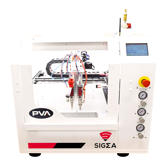
Sigma Operation Manual System Description T he Sigma benchtop is a compact three-axis robotic gantry ideal for automating a variety 2 2 7 B 2 2 7 B of dispensing and coating applications. Featuring multiple mounting positions, users can easily incorporate multiple chemistries or application techniques into their process. With remote programming capability and image background import, programs can be quickly uploaded from your desktop utilizing Sigma’s internal 2.4 GHz Wi-Fi network. -
Page 11: Environmental
2 4 8 B 2 4 8 B solvent compatible with the application material and workcell components. N ote: PVA is not responsible for damages incurred by incorrect transportation and 4 5 6 B 4 5 6 B handling of the workcell. The instructions given for the transportation, handling, and storage of the workcell are the correct manufacturer’s procedure. -
Page 12: Installation And Setup
Sigma Operation Manual Installation and Setup B efore you operate the workcell, know the components. Do the steps in this manual for 2 4 9 B 2 4 9 B safe and correct operation. W arning: Only qualified personnel should do these procedures. Obey this manual and 4 5 7 B 4 5 7 B all applicable safety regulations. -
Page 13: Inspection
Sigma Operation Manual Inspection O pen the doors and remove all straps, tie wraps, and sponges around the dispense 2 5 7 B 2 5 7 B heads and gantry. In order to prevent any movement during the shipping process, many workcells are equipped with green shipping brackets inside the machine. -
Page 14: Power Up
2 6 6 B 2 6 6 B power equipment uses the same source, a line conditioner may be necessary. Poor power quality can cause machine errors. All workcells shipped from the PVA factory can operate with the voltage used at the installation site, per engineering design. -
Page 15: F Igure 3: Main Power Switch
N OTE: Refer the Material Safety Data Sheets (MSDS) for safety precautions on any 4 6 1 B 4 6 1 B chemicals used in PVA equipment. N OTE: Do not power on the workcell or add material to the pressure vessels until they 4 6 2 B 4 6 2 B are correctly grounded. -
Page 16: Necessary Downloads
P rior to operating Sigma, please visit contact.pva.net/sigma-manual to download a copy 2 8 2 B 2 8 2 B of the manual, Inkscape, and the PVA G-code Generator. This URL should be included on your machine. A ccess contact.pva.net/sigma-manual via browser. -
Page 17: Sigma Manual
Sigma Operation Manual Sigma Manual T he Sigma manual will walk you through how to install and operate Sigma as well as how to 2 8 4 B 2 8 4 B use Inkscape and the web interface. Read this manual carefully prior to use. -
Page 18: Download Inkscape
Sigma Operation Manual Download Inkscape S igma is designed to work exclusively with Inkscape version 0.92.4. Prior to use, Inkscape 2 8 6 B 2 8 6 B version 0.92.4 must be downloaded. C lick Download Inkscape. 9 0 B 9 0 B C hoose between 32-bit and 64-bit. -
Page 19: Install Pva G-Code Generator Extension
Sigma Operation Manual Install PVA G-code Generator Extension P rior to use, the PVA G-code Generator extension must be installed within Inkscape. 2 8 8 B 2 8 8 B C lick G-code Generator. 9 3 B 9 3 B W hen the screen opens, select all files and click Download. -
Page 20: Operating Safety
W arning! The safety features should NEVER be bypassed, disabled, or tampered with. 4 6 3 B 4 6 3 B PVA is not responsible for any damage, mechanical or human, caused by changes or destruction of any safety features. -
Page 21: Standard Machine Exhaust Requirements
N ote: Refer the Material Safety Data Sheets (MSDS) for safety precautions on any 4 6 5 B 4 6 5 B chemicals used in PVA equipment. N ote: The safety devices on your workcell will be different with each model. -
Page 22: Inkscape
3 0 2 B 3 0 2 B to convert what is drawn in Inkscape to a G-code file that can be uploaded to Sigma. Sigma is designed to work with Inkscape version 0.92.4. Inkscape must be downloaded prior to use. -
Page 23: Setup
1 1 B 1 1 B T he Document Properties popup window will display. Under Custom Size, set the 9 9 B 9 9 B Sigma workspace dimensions (330 mm X 300 mm). Note: If a template has already been created for the workspace dimensions, select New From Template. -
Page 24: Open A Template
Sigma Operation Manual Open a Template T o open a pre-existing template, select File New from Template. 1 0 0 B 1 0 0 B T he New From Template window will open. 3 0 8 B 3 0 8 B... -
Page 25: Create A New Layer
Sigma Operation Manual Create a New Layer S elect Layer Add Layer or Shift+Ctrl+N. 1 0 4 B 1 0 4 B E nter a Layer Name for the substrate and click Add. 1 0 5 B 1 0 5 B... -
Page 26: Import Image (Optional)
Sigma Operation Manual Import Image (Optional) T here is an option to import an image of the substrate as a reference for the dispense path. 3 1 4 B 3 1 4 B Ensure that the reference image is scaled correctly. Skip this section if it does not apply. -
Page 27: F Igure 19: Image Example
Sigma Operation Manual N ote: There is also an option to paste the image onto the active layer. Simply use 4 6 7 B 4 6 7 B Ctrl+V to paste the image onto the workspace. T he image will display in the workspace window and can be resized. -
Page 28: Transform Image
Sigma Operation Manual Transform Image R esize the substrate image to its accurate size. 3 1 9 B 3 1 9 B S elect the image. 1 1 0 B 1 1 0 B S elect Object Transform or Ctrl+Shift+M to open the Transform panel. This 1 1 1 B 1 1 1 B panel offers the ability to Move, Scale, Rotate, and Skew the image if necessary. -
Page 29: Move Tab
Sigma Operation Manual Move Tab U se the Move tab to translate an object. An object can be moved horizontally or vertically. 3 2 1 B 3 2 1 B Use the arrows or enter a value manually in the field. -
Page 30: Rotate Tab
Sigma Operation Manual Rotate Tab U se the Rotate tab to rotate an object. An object will be rotated relative to Rotation center. 3 2 7 B 3 2 7 B The direction of the rotation is positive in the counterclockwise direction. -
Page 31: Move Image
Sigma Operation Manual Move Image T here are three options to move the image to match its location on the workspace. 3 3 2 B 3 3 2 B N ote: The X and Y coordinates will be the left-hand corner of the image. -
Page 32: Lock Layer
Sigma Operation Manual Lock Layer A fter the substrate image is resized and positioned in the desired location, PVA 3 3 4 B 3 3 4 B recommends locking the layer. There are two ways to lock a layer. •... -
Page 33: Create Dispense Path
Sigma Operation Manual Create Dispense Path T his section will review how to create a dispense path. It is recommended that each tool 3 3 6 B 3 3 6 B have a unique layer for its dispense path. N ote: The robot will follow the dispense path based on the direction that a line was 4 7 0 B 4 7 0 B created. -
Page 34: Edit A Line
Sigma Operation Manual C ontinue drawing additional segments if necessary. 1 2 1 B 1 2 1 B H it Enter to complete the line or click on the first endpoint when placing the last 1 2 2 B 1 2 2 B endpoint. -
Page 35: Create A Circle
Sigma Operation Manual Create a Circle C ircles are used to represent dispense dots. If a full circle is drawn, the center point of the 3 4 0 B 3 4 0 B circle is where the valve will dispense. -
Page 36: Create An Arc
Sigma Operation Manual Create an Arc I f an arc is drawn, the path will follow the start point of the arc to the end point. 3 4 3 B 3 4 3 B U se the Select tool to select the circle that should be changed to an arc. -
Page 37: Edit An Arc
Sigma Operation Manual Edit an Arc U se the Select tool and select the arc that needs to be edited. 1 4 0 B 1 4 0 B T o resize the arc, use the white arrows. 1 4 1 B 1 4 1 B... -
Page 38: Set Fill And Stroke
Sigma Operation Manual Insert new nodes into selected segments. Clicking on the path will select the nearest node on both sides of the point where the path was clicked. Double- clicking on the path will also insert a node. Delete selected nodes. -
Page 39: F Igure 40: Fill And Stroke Option 2
Sigma Operation Manual U se Shift + Ctrl + F. 1 4 8 B 1 4 8 B 3 5 0 B 3 5 0 B F igure 40: Fill and Stroke Option 2 4 0 B 4 0 B N avigate to the fill and stroke area on the bottom left of the screen. -
Page 40: Edit Path Order
Sigma Operation Manual Edit Path Order B y default, the G-code will follow the order in which the dispense path was created. It will 3 5 3 B 3 5 3 B be generated from the upper most layer to the bottom layer. In the event that an application requires certain areas to be coated first or you need to reduce cycle time, the layers and path objects can be viewed and modified via the Objects window. -
Page 41: Pva Gcode Generator
Sigma Operation Manual PVA Gcode Generator T he PVA Gcode Generator is an extension that will create a G-code based on what is drawn 3 5 6 B 3 5 6 B in Inkscape. T o open PVA G-code Generator, select Extensions PVA PVA Gcode 1 5 1 B 1 5 1 B Generator. -
Page 42: Build Path
Sigma Operation Manual Build Path T he Build Path tab builds the G-code file. Each active layer will need layer settings and 3 6 0 B 3 6 0 B each selected object will need settings applied before the G-code file can be built. -
Page 43: Layer Settings
P rior to generating the G-code file, you can view layer settings to make any changes. 3 6 7 B 3 6 7 B S elect the desired layer and select Extensions PVA PVA Gcode Generator. 1 5 6 B 1 5 6 B N avigate to Layer Settings. -
Page 44: Travel Speed
F igure 49: Edit Layer Settings 4 9 B 4 9 B O pen the PVA Gcode Generator and navigate to Layer Settings. 1 6 2 B 1 6 2 B U nder the Action dropdown, select Import Layer Settings from Displayed. -
Page 45: Path Object Settings
3 7 6 B 3 7 6 B Tool A ssigns a tool to the objects that are selected. If there are two tools on Sigma, the left tool 3 7 7 B 3 7 7 B is T0 and the right tool is T1. -
Page 46: Line Specific Settings
Sigma Operation Manual Line Specific Settings • D ispense Speed (mm): The dispense speed for the selected objects. 1 6 4 B 1 6 4 B • V alve Off Distance: The distance that the valve should be closed before the end of 1 6 5 B 1 6 5 B the selected line. -
Page 47: Operation
S igma has 2.4GHz wireless network connection capability that allows Sigma to be operated 3 7 9 B 3 7 9 B remotely with a computer. For the initial setup of Sigma, you will need to use this feature. T urn on Sigma using the on/off switch located near the power cord connection. -
Page 48: F Igure 52: Sigma Web Interface Home Screen
T he web interface will display. 3 8 1 B 3 8 1 B 3 8 2 B 3 8 2 B F igure 52: Sigma Web Interface Home Screen 5 2 B 5 2 B Page 48 of 69... -
Page 49: Connect Web Interface To Existing Network
N ote: This option is not compatible with 5 GHz networks. 4 7 3 B 4 7 3 B U se the steps outlined in Sigma Wireless Connection Setup to connect to Sigma’s 1 7 5 B 1 7 5 B WiFi network. -
Page 50: F Igure 54: Enter M587 Command
Sigma Operation Manual E xample: 3 8 8 B 3 8 8 B Network SSID TEST_Network Network Password Testing123 IP Address 1.160.10.240 U sing the credentials listed above, the M587 command would be as follows: 3 8 9 B 3 8 9 B M 587 S”TEST_Network”... -
Page 51: Change Web Interface To Client Mode
Sigma Operation Manual Change Web Interface to Client Mode T o switch the web interface network from host mode to client mode, select 1 9 2 B 1 9 2 B Settings. S elect System Editor. 1 9 3 B 1 9 3 B N avigate to the config.g file and right click. -
Page 52: F Igure 57: Change Network
Sigma Operation Manual D elete the semicolon (;) from M552 S1. 1 9 7 B 1 9 7 B A dd a semicolon (;) to M552 S2 to select the network. 1 9 8 B 1 9 8 B 3 9 5 B 3 9 5 B... -
Page 53: F Igure 60: Sigma Control Screen Wifi Confirmation
F igure 60: Sigma Control Screen WiFi Confirmation 6 0 B 6 0 B N ote: Sigma can also be powered down so the SD card storing the config.g file can be 4 7 5 B 4 7 5 B removed from the controller. -
Page 54: Uploading G-Code To Sigma
F rom the Sigma web interface, select Upload & Start. 2 0 2 B 2 0 2 B C hoose the desired G-code file. Once uploaded, Sigma will run the dispense path. 2 0 3 B 2 0 3 B... -
Page 55: Job Status
Sigma Operation Manual Job Status J ob Status will display the progress of the current path. You can also change speed, pause 4 0 7 B 4 0 7 B the job, or start another job when the path is complete. -
Page 56: F Igure 65: Upload G-Code File
Sigma Operation Manual F iles can be uploaded by browsing for them or dropping them onto the Upload G Code 4 1 2 B 4 1 2 B Files(s) button. The file upload functionality cannot be used during while the machine is running. -
Page 57: Macros
Sigma Operation Manual 4 1 6 B 4 1 6 B F igure 67: Edit G-Code 6 7 B 6 7 B Macros M acros allows you to upload and edit user-defined macros. 4 1 7 B 4 1 7 B... -
Page 58: Control Screen Overview
Sigma Operation Manual Control Screen Overview T he control screen on Sigma has the same features and functionality of the web interface. 4 1 9 B 4 1 9 B The two can be used interchangeably. 4 2 0 B 4 2 0 B... -
Page 59: F Igure 71: Move Axis (Control)
Sigma Operation Manual Move Individual Axis 4 2 2 B 4 2 2 B F igure 71: Move Axis (Control) 7 1 B 7 1 B Access Macro Files 4 2 3 B 4 2 3 B F igure 72: Access Macro Files (Control) -
Page 60: F Igure 73: Print Screen
Sigma Operation Manual Print Screen 4 2 4 B 4 2 4 B F igure 73: Print Screen 7 3 B 7 3 B G-code Console Quick Access Macros Page 60 of 69 Revision C March 2023... -
Page 61: Maintenance
Sigma Operation Manual Maintenance Perform the preventative maintenance as shown in the table below to increase the life of the workcell and make sure every run is high quality. Note: Only qualified personnel should perform workcell maintenance. Service Area Every Shift... -
Page 62: Technical Support
P VA uses an automated ticketing system called Team Support. The fastest way to contact 4 2 6 B 4 2 6 B PVA for any technical support is to create a ticket. The ticketing system alerts the service department of your region and assigns a service engineer. All service engineers can see the information for each ticket for collaborate responses to more difficult problems from our global team. -
Page 63: F Igure 75: Log In
Sigma Operation Manual S elect “Log In” to log in to your account or create a new one. 4 2 9 B 4 2 9 B 4 3 0 B 4 3 0 B F igure 75: Log In 7 5 B 7 5 B T he Sign In screen will be shown. -
Page 64: F Igure 78: Complete The Ticket
4 3 8 B 4 3 8 B F igure 78: Complete the Ticket 7 8 B 7 8 B I f you cannot access the PVA Support Portal, email customer service at cs@PVA.net 4 3 9 B 4 3 9 B to create a ticket. -
Page 65: F Igure 80: Pva Support Hub
Sigma Operation Manual Y ou can also access the PVA Support Hub from “PVA Support Hub” option in the 4 4 1 B 4 4 1 B header or through the link https://support.pva.net/. The support hub has processes and procedures on common topics and issues, including the Sigma manual. -
Page 66: Table Of Figures
4 8 1 B F igure 6: Download Inkscape ....................... 18 4 8 2 B F igure 7: Install PVA G-code Extension 1 ................... 19 4 8 3 B F igure 8: Install PVA G-code Extension 2 ..................19 4 8 4 B F igure 9: Access Inkscape Manual ..................... - Page 67 5 2 5 B F igure 50: Path Object Settings Tab ....................45 5 2 6 B F igure 51: Sigma Serial Number Wi-Fi Network ................47 5 2 7 B F igure 52: Sigma Web Interface Home Screen ................48 5 2 8 B F igure 53: G-code Console ........................
-
Page 68: Notes
Sigma Operation Manual Notes Page 68 of 69 Revision C March 2023... -
Page 69: Warranty
PVA (or from factory authorized dealers) will void all warranties. A ll PVA warranties extend only to the original purchaser. Third party warranty claims will not 4 4 7 B 4 4 7 B be honored at any time.
Need help?
Do you have a question about the Sigma and is the answer not in the manual?
Questions and answers