Table of Contents
Advertisement
Quick Links
Advertisement
Table of Contents

Summary of Contents for NewTek Connect
- Page 1 NewTek Connect Studio Input/Output Module User Guide...
- Page 2 Trademarks: NDI, TriCaster, 3Play, TalkShow, Video Toaster, LightWave 3D, and Broadcast Minds are registered trademarks of NewTek, Inc. MediaDS, Connect Spark, LightWave, and ProTek are trademarks and/or service marks of NewTek, Inc. All other products or brand names mentioned are trademarks or registered trademarks of their respective holders.
-
Page 3: Table Of Contents
T A B L E O F C O N T E N T S CHAPTER 1 INTRODUCTION AND SETUP ....................5 Section 1.1 Welcome ................................... 5 Section 1.2 Overview ................................... 5 Section 1.3 Setting Up .................................. 6 1.3.1 Command and Control ..............................6 1.3.2 Input/Output connections .............................. -
Page 5: Chapter 1 Introduction And Setup
WELCOME SECTION 1.1 Thank you for purchasing this NewTek product. As a company, we are extremely proud of our record of innovation and commitments to excellence in design, manufacture, and superb product support. NewTek’s innovative live production systems have repeatedly redefined broadcast workflows, providing new possibilities and economy. -
Page 6: Section 1.3 Setting Up
1. Connect an external computer monitor to the HDMI A word about UPS devices: port on the backplate (see Input/Output connections). 2. Connect the mouse and keyboard to USB ports also on ‘Modified sine wave’ UPS devices are the backplate. -
Page 7: Input/Output Connections
FIGURE 1 1. HDMI – monitor port 2. Ethernet – network connections 3. USB – connect keyboard, mouse and other peripheral devices 4. Motherboard audio connectors 5. Genlock and SDI In/Out – current generation units (designated ‘Mark M’) provide HD-BNC connectors (High Density BNC);... -
Page 8: Chapter 2 User Interface
This chapter explains the layout and options of the user interface, and how to configure NC1 IO audio and video input and output. It also introduces the various supplemental video production features NewTek IO provides, including Proc Amps, Scopes and capture. THE DESKTOP SECTION 2.1... -
Page 9: Configure Channels
CONFIGURE CHANNELS 2.1.1 NC1 IO allows you to select different audio and video sources for each channel via the Configure panel ( Figure 4). Click the gear next to the channel label below a viewport to open its Configure panel (Figure 3). FIGURE 3 NPUT FIGURE 4... - Page 10 See also Appendix A: Key/Fill Connections for key/fill connection details. A Delay setting is provided for both audio and video sources, allowing precise A/V synchronization where a/v source timing differs. IP S LIPS AND OURCES As mentioned in the previous section, an IP (network) source –...
- Page 11 To use click the Add New IP Source menu, select a source type from the dropdown list provided. This opens a dialog suited to the particular source device you wish to add, such as one of the numerous supported PTZ camera brands and models, as shown in Figure 8.
- Page 12 UTPUT The second tab in the Configure Channel pane hosts settings related to output from the current channel. FIGURE 9 NDI O UTPUT Output from channels assigned to local SDI input sources is automatically sent to your network as NDI signals.
- Page 13 The Supplemental Audio Device allows you to direct audio output to system sound devices as well as well as any supported third part audio devices you may connect (typically by USB). As required, Audio Format options are provided in a menu at right.
-
Page 14: Section 2.2 Titlebar & Dashboard
OLOR The Color tab provides an extensive set of tools for adjusting the color characteristics of each video channel. Choosing Auto Color automatically adapts color balance as lighting conditions change over time. Note: Proc Amp adjustments follow Auto Color processing. By default, each camera with Auto Color enabled is processed by itself. -
Page 15: Titlebar Tools
1. Machine name (the system network name supplies the prefix identifying NDI output channels) 2. NDI KVM menu – Options to control NC1 IO remotely via NDI connection 3. Time Display 4. Configuration (see Section 2.2.1) 5. Notifications Panel 6. Headphones Source and Volume (see Section 2.2.6) 7. -
Page 16: System Configuration (Mark M)
SYSTEM CONFIGURATION (MARK M) 2.2.2 MARK M The System Configuration dialog is opened by clicking the ‘gear’ gadget next to the Titlebar time display, and appears as shown in Figure 15. LTC T IMECODE LTC timecode support can be activated by choosing an input using the LTC Source menu to choose almost any audio input to receive the timecode signal over, and enabling the checkbox at left. - Page 17 The IO Configuration tab makes it a simple matter to select presets using graphic representations that reference which ports will be input vs output, as well as show the port numbering and Alpha supporting connections, as shown in the red circle in Figure 16.
- Page 18 If your equipment allows you to do so, you should genlock all hardware sources supplying NC1 IO, and the NC1 IO unit. To connect the genlock source, supply the reference signal from the ‘house sync generator’ to the Genlock connector on the backplane.
-
Page 19: System Configuration (Mark D)
If your equipment allows you to do so, you should genlock all hardware sources supplying NC1 IO, and the NC1 IO unit. To connect the genlock source, supply the reference signal from the ‘house sync generator’ to the Genlock connector on the backplane. The unit can auto-detect an SD (Bi-level) or HD (Tri-level) reference. -
Page 20: Notifications
The presets graphically display various i/o configurations as viewed from the rear of the system. Simply click a configuration preset to select it. Note: Configuration changes require you to either reboot the system, or simply to restart the application. NOTIFICATIONS 2.2.4 The Notifications panel opens when you click the ‘text balloon’... -
Page 21: Viewport Tools
VIEWPORT TOOLS 2.2.5 FIGURE 22 NC1 IO's channels each have a toolbar beneath their respective viewports. The various elements comprising the toolbar are listed below from left to right: 1. Channel name – Can be changed by clicking on the label, and also in the Configure Channel panel. a. -
Page 22: Dashboard Tools
2.2.6 UDIO EADPHONES You can connect a headset to the (green) audio output jack on the rear of NC1 IO's motherboard. FIGURE 27 Controls for Headphone audio are found in the lower-left corner of the dashboard at the bottom of the screen Figure 27). - Page 23 ISPLAY In the bottom-right corner of the Dashboard at the bottom of the (primary) screen, the Display widget offers a variety of layout options to let you view channels individually (Figure 30). FIGURE 30 Waveform and Vectorscope features are shown when you select the SCOPES option in the Display widget (Figure 31).
-
Page 25: Appendix A: Key/Fill Connections
APPENDIX A: KEY/FILL CONNECTIONS A.1 MARK M SYSTEMS Key/Fill output using two SDI output connectors is supported as follows: SDI connectors numbered 1-4 show “video and alpha” options in their Configure Channel Format • menu. Selecting this option sends ‘video fill’ from the source to the designated SDI connector (let’s refer to it as SDIn), and places the ‘matte’... -
Page 26: Appendix B: Ndi ® (Network Device Interface)
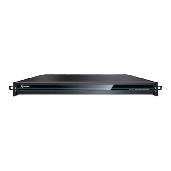
NC1 IO is designed for convenient mounting in a standard 19” rack (mounting rails are available separately from NewTek Sales). The unit comprises a 1 Rack Unit (RU) chassis supplied with ‘ears’ designed to permit mounting in standard 19” rack architecture. -
Page 27: Appendix D: Enhanced Support (Protek)
We know our products play vital roles in the productions of our customers. Durability and consistent, robust performance are much more than just adjectives for your business and ours. For this reason, all NewTek products undergo rigorous reliability testing to ensure they meet our exacting test standards. For NC1 IO, the following standards are applicable:... -
Page 29: Credits
Trademarks: NDI, TriCaster, 3Play, TalkShow, Video Toaster, LightWave 3D, and Broadcast Minds are registered trademarks of NewTek, Inc. MediaDS, Connect Spark, LightWave, and ProTek are trademarks and/or service marks of NewTek, Inc. All other products or brand names mentioned are trademarks or registered trademarks of their respective... - Page 31 Copyright © 1990-2021 NewTek Inc. San Antonio TX USA...
Need help?
Do you have a question about the Connect and is the answer not in the manual?
Questions and answers