Table of Contents
Advertisement
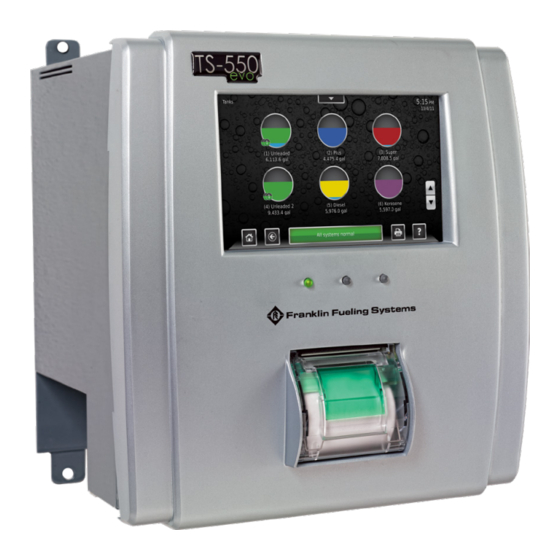
TS-550/5000 evo
®
Fuel Management System
Installation Guide
Manual #
Revision
Date
Changes from Previous Revision
000-2170
D
June 2019
Added new control drawings 000-1722_015_01_1814098 and
000-1722_015_02_1446163
Franklin Fueling Systems • 3760 Marsh Rd. • Madison, WI 53718 USA
Tel: +1 608 838 8786 • 800 225 9787 • Fax: +1 608 838 6433 • www.franklinfueling.com
Advertisement
Table of Contents


Need help?
Do you have a question about the TS-550 evo and is the answer not in the manual?
Questions and answers