
Related Manuals for milleteknik EN54

Summary of Contents for milleteknik EN54
- Page 1 EN54 EN54 24V 5A FLX M, EN54 24V 10A FLX M, EN54 24V 15A FLX M, EN54 24V 25A FLX M...
- Page 2 350-157 Publication date 2023-03-08...
-
Page 3: Table Of Contents
8. Alarm displayed on cabinet door ....................20 9. Product sheet - technical data ....................21 9.1. EN54-4 Certified / SBF110:8 Approved battery backup ............ 21 9.1.1. Name, article number, e-number and certificate number ........22 9.1.2. About EN54 ....................... 22 Flexibility ...................... -
Page 4: Revisions And The Edition Of This Document
10. Address and contact details ....................35 1. REVISIONS AND THE EDITION OF THIS DOCUMENT The current and most recently published edition of this document is available at www.milleteknik.se. Audit log can be requested, see contact information for address or e-mail address. - Page 5 READ THIS FIRST! 100 mm free space must be left on the top and bottom. Electronics, regardless of enclosure, are intended for use in a controlled indoor envi- ronment. Ventilation must not be covered. Only authorized persons should install and maintain the system. It is the installer's responsibility to ensure that the system is suitable for its intended use.
-
Page 6: Component Overviews
2. COMPONENT OVERVIEWS 2.1. Component overview Table 1. Component overview Letter Explanation Bracket, reversible for wall mounting or 19 "rack. Sabotage contact. If alarm class 3 (SSF) is to be met, the tamper switch must be on the wall. Cabinet in powder-coated sheet metal. Place for mounting of optional cards. -
Page 7: Mounting On A Wall Or In A 19 "Rack
Explanation Clip in bracket that secures the bracket to the housing. Holes for screws - can be used to secure the bracket in the housing. The brackets is screwed to a wall or 19 "rack. 3.2. Mounting on a wall or in a 19 "rack The unit can be mounted in a 19 ”rack or on a wall. -
Page 8: Mounting
4. BATTERIES - PLACEMENT AND CONNECTION 4.1. Placement of batteries Table 2. Batteries to be installed to maintain certification EN54 24V 5A-25A FLX M 20 Ah IMPORTANT Requirements for battery replacement according to EN 50131-6: Batteries must be new during installation and battery replacement. -
Page 9: Connecting Batteries In Flx M
4.2. Connecting batteries in FLX M Figure 2. Connection of batteries in FLX M. Motherboards may differ depending on the configuration, but connection of batteries takes place in the same way. Explanation Fuse. Minus coil for battery cable from 4. Plus terminal for battery cable from 4. -
Page 10: Connection Of Batteries In Flx S, Flx M And Flx L
4.4. Connection of batteries in FLX S, FLX M and FLX L Battery wiring is mounted on the circuit board upon delivery. Pictures below only show how to connect wiring. Place the batteries in the cabinet with the battery terminals facing outwards. Connect the battery cable. -
Page 11: How Ferrites Are Mounted On Cables
A "pass" is how many times the cable passes through the ferrite. A ferrite can either be threaded through the cable, this counts as one pass (1). A cable looped through the ferrite counts as two passes (2). A ferrite on EN54 shall be threaded one pass on load cables (A). -
Page 12: Pcb Description Of Pro2V3
A ferrite must be shall be threded one pass on the mains power cable (B). 6. PCB DESCRIPTION OF PRO2V3 The motherboard controls the device, distributes power and communicates with other systems. See technical data for more information. Figure 5. PRO2 v3 Table 4. -
Page 13: Fuses
No . On circuit board Explanation Connection external fuse (NO). J7/21 Connection to external fuse (NC). P1:1-3 Incoming mains, (230 V). L, N, PE. 6.1. Fuses Table 5. Fuses on PRO2 / PRO2 V3 Fuse Type Explanation T16A Mains fuse Load fuse 2 + (for P2: 4) Reading protection 1 + (for P2: 1) T2.5A / T4A... -
Page 14: Connect Load
ELECTRICAL MAINS CONNECTION 230 V AC ON CIRCUIT BOARD Check that the marking on the circuit board matches the cable arrangement on the terminal block. 6.3. Connect load MAX CURRENT Maximum current must not be exceeded. Maximum current is indicated on the CE- marking on the unit. -
Page 15: Load Cards With Blade Fuses
Figure 7. Effect card The effect card increases the current for 15 A and 25 A units. 6.5. Load cards with blade fuses The card replaces the load output on the motherboard. The load card has a different type of fuse that is easier to change and at the same time the card provides a easier connection of the load. -
Page 16: Alarm Via Communication
6.6. Alarm via communication Connection of communication to the parent system takes place via JU6. See the parent system docu- mentation for more information. 6.7. Communication to a parent system It is possible to connect communication to a parent system via connections on P2: 5-13. See also parent system documentation for compatible protocol. -
Page 17: Dip Switch 1-8
6.9. Dip switch 1-8 Dip-Switch has several different configuration modes: Table 11. Dip switch 1-8 Dip switch In mains operation or in battery operation Comment Address for external communication. Address for external communication Address for external communication Address for external communication Sets alarm for mains failure delay Available from software v1.5 Sets alarm for mains failure delay... -
Page 18: Low Battery Level (Dip 7)
6.9.3. Low battery level (dip 7) Dip: 7 has the same function regardless of whether the unit is in mains or battery operation or whether the tamper switch is held down. Table 14. Low battery level Alarm for low battery level is given Dip 7 22,8 V* 24 V... -
Page 19: Alarm Card For Pro2
Reset jumper. Indicator diode, flashes green during normal operation. 5,5.1, 5.2 P5:1-3 NO, COM, NC Tamper alarm, (optional for EN54). 5.1 Relay. 5.2 LED, lights up green when relay is energized. 6, 6.1, 6.2 P5:4-6 NO, COM, NC Alarm for: Low system voltage. 6.1 Relay. 6.2 LED, lights up green when relay is energized. -
Page 20: Commissioning - How To Start The Unit
7. COMMISSIONING - HOW TO START THE UNIT Connect batteries Connect / switch on fuses connect load, alarm and possibly. other connections. Screw the mains cable into the terminal block and attach the terminal block to the motherboard. Switch on mains voltage. The unit works normally when the indicator LED on the outside of the cabinet door lights up with a solid green light. -
Page 21: Product Sheet - Technical Data
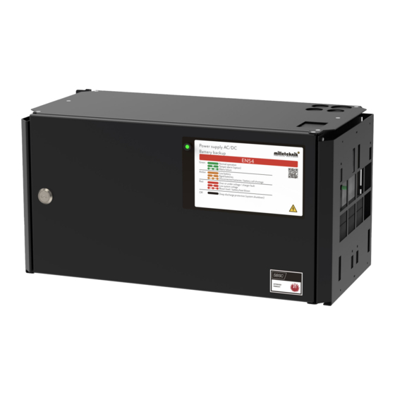
When operating system: If the indicator LED is off, deep discharge protection has come into force. 9. PRODUCT SHEET - TECHNICAL DATA 9.1. EN54-4 Certified / SBF110:8 Approved battery backup Figure 8. EN54 FLX M The battery backup can be mounted on a wall or in a 19" rack. -
Page 22: Name, Article Number, E-Number And Certificate Number
• Flexible battery capacity with battery boxes extends backup operating time. FLEXIBILITY EN54 can be mounted with 1-4 extra battery boxes. The battery boxes and shelves are connected via a 9-pin connector. The battery box has room for up to 2 pcs. 45 Ah batteries per battery box. -
Page 23: Regulations And Certifications
SS-EN 50 130-4: 2011 Edition 2, EN50131-6 9.2.3. Translation table certified / marketed units Certified name: Marketed as: NOVA 27 50-FLX EN54 24V 5A FLX M NOVA 27 100-FLX EN54 24V 10A FLX M NOVA 27 150-FLX EN54 24V 15A FLX M... -
Page 24: Spare Operating Times, Power Outlet And Load Output Power
9.3. Spare operating times, power outlet and load output power 9.3.1. Load current EN54 Table 15. EN54 24V 5A FLX M Battery size Maximum Maximum Power outlet i recharge time network operation to 80% (Imax. A) 20 Ah 3.5 A... -
Page 25: Reserve Operating Times For Different Alarm Classes - Overview
Maximum charging current with recharging (ie maximum charging current at the same time as batteries are charged): 14 Ah. Maximum power outlet in battery mode (same as Imax. B): 15A Table 18. EN54 24V 25A FLX M Battery size Maximum... -
Page 26: Circuit Boards - Technical Data
• Low system voltage, system voltage below 24.0 V in mains operation. • Low battery voltage, below 24.0 V DC, or mains interruption. • Power failure alarm. • Sabotage switch. Optional for EN54. • Fuse fault. • Aged battery Expanding alarm functions are available via communication or with alarm cards. -
Page 27: Technical Data, Alarm Cards For Pro 2 And Pro2 V3
Table 20. Fuses Fuses Type 1.5 A F1.5A 10 A T10A 15 A T15A 25 A T25A Power supply fuse of 12V one T2.5AH250V. Ceramic. Mains fuse for 24 V units up to 15 A T2.5AH250V. Ceramic. Mains fuse for 24 v units over to 15 A T4AH250V. -
Page 28: Power Supply
* Alarm on potential-free relay contact. ** System voltage in mains operation is below 24.0 V. 350-232 9.5. Power supply 9.5.1. Power supply - Technical Data DR-120-24 Sits in EN54 24V 5A FLX M Info Explanation Output voltage 27.3 V Output current:... -
Page 29: Power Supply - Technical Data Hrp-600-24
Use of power supplies coming from another source may cause damage not covered by the warranty. Warranty is canceled if power supplies (from a source other than support / designated by support) that are not correctly calibrated are used. 9.5.3. Power supply - Technical Data HRP-600-24 EN54 24V 25A FLX M Info Explanation Output voltage 27.3 V... -
Page 30: Technical Data Enclosures
Milleteknik provides support during the product's lifetime, however, no later than 10 years after the date of purchase. Switching to an equivalent product may occur if Milleteknik deems that repair is not possible. Support may be added (at Millteknik's desrection) after the warranty period has expired. -
Page 31: Spare Parts
9.8.5. Country of manufacture Country of manufacture / country of origin is Sweden. For more information, contact your seller. 9.8.6. Designed and produced by: Milleteknik AB Designed and produced by Milleteknik AB 9.9. Batteries - recommended, not included 9.9.1. Batteries are not included they are sold separately Batteries are sold separately. -
Page 32: Battery Combinations
2 and Batteribox 3 2 and Batteribox 4 9.9.3. Battery combinations Battery combinations possible with EN54 5A FLX M EN54 10A FLX M EN54 15A FLX M EN54 25A FLX M Table 23. Battery combinations for FLX M and battery box 24V FLX M... -
Page 33: Ah, 12 V Agm Battery
Battery capacity Number of batteries Unit + battery box 135 Ah 2 pcs 45 Ah* 24V 5A-10A FLX M 2 pcs 45 Ah* Battery box 24V FLX M 2 pcs 45 Ah* Battery box 24V FLX M 155 Ah 2 pcs 20 Ah 24V 5A-10A FLX M 2 pcs 45 Ah* Battery box 24V FLX M... -
Page 34: Reserve Operating Times For Different Alarm Classes - Overview
* Design Life is the durability this year for unused battery. Environmental factors such as heat and load affect service life. Batteries that have a durability (+10 Design lLife) of 10+ years usually need to be replaced after 4-5 years. 9.9.6. -
Page 35: Address And Contact Details
2365 2670 2945 1577 1780 1960 1500 1558 1800 10 A 1140 1246 1410 12 A 1038 1200 14 A 1055 16 A 18 A 20 A Subject to typos. 10. ADDRESS AND CONTACT DETAILS Milleteknik AB Ögärdesvägen 8 B... - Page 36 S-433 30 Partille Sweden +46 31 340 02 30 info@milleteknik.se www.milleteknik.se...
Need help?
Do you have a question about the EN54 and is the answer not in the manual?
Questions and answers