Table of Contents
Advertisement
Quick Links
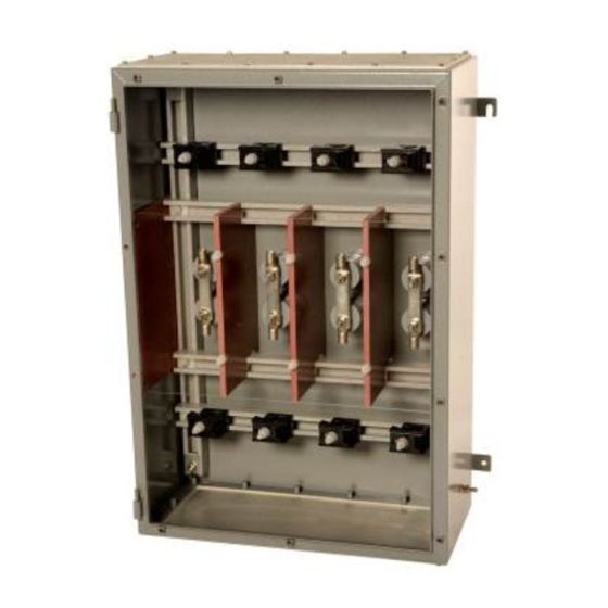
INSTALLATION, OPERATION & MAINTENANCE INSTRUCTIONS FOR
ABTECH 'HVJB' series – CML16ATEX3324 and IECEx CML 16.0100
Installation
Note
When this product is to be used in high operating temperature mode the cable insulation material must be
suitable for that operating temperature.
1) Using the mounting dimensions provided, either in the product catalogue data sheets or on the drawings
supplied (as part of the project documentation) mark out the positions for the mounting holes on the surface
where installation is required.
2) Drill the mounting holes for either M10 fixing studs.
3) Insert the top two studs leaving 8 to 10mm protruding and lift the enclosure into position using such
assistance as may be necessary to avoid injury and hang the top fixing brackets of the box onto the studs.
Note: When lifting eye-bolts are provided note the limits given on the instruction document ABTQ-231
Ensuring that the box is secure, insert and tighten the bottom two studs. Now complete tightening the top
two studs.
4) Unfasten the lid securing screws and remove the enclosure lid. Put the lid in a safe place.
5) Install and secure the cable glands in accordance with the manufacturer's instructions.
Main Power Cable Connections
6) Remove the top half on each power core cable clamp and put safely aside.
7) Remove the terminal post lock nuts, washers and the upper current bars and put safely aside.
8) Pull the cables into the box leaving trailing leads long enough to reach their respective crimp lugs after
routing through the cable clamps.
9) Trim each cable core so that the conductor end will reach the inside stop of the crimp lug on which it is to be
terminated.
10) Strip the insulation of each cable core by the length of the crimping barrel plus 2mm.
11) Remove each crimping lug in turn from the terminal post and place the securing nuts to one side.
12) Insert the conductor into the crimp lug barrel, ensuring that all strands of the conductor enter the barrel. This
will ensure that minimum clearance distances are not compromised by stray strands.
13) Crimp each lug onto the respective conductor using Cembre die sets or equivalent. Ensure that the crimp
die set used is suitable for the conductor size and is not damaged or excessively worn. The crimp die set
may produce either a hexagon type crimp or an indent type crimp. With hexagon die sets execute at least
two crimps on each lug.
14) Route the cable core through the appropriate cable clamp and place the hole in the palm of the now
attached cable lug on to its respective terminal post, on top of the lower current bar.
Abtech Ltd.
Newhall Road, Lower Don Valley, Sheffield S9 2QJ
Marking (standard temperature)
The maximum power dissipation and voltage
permitted in this terminal box are marked on the
label and identified as
temperature range for which this product is suitable
is either–20
o
C to +40
o
C or –50
the narrower ambient range (shown left) is applicable
it need not be included.
The IP66 rating is an example and may read IP66,
IP67 or IP68
Marking (high operating temperature)
The maximum power dissipation and voltage
permitted in this terminal box are marked on the
label and identified as ***W and __kV. The ambient
temperature range for which this product is suitable
o
o
is –50
C to +55
C.
The IP66 rating is an example and may read IP66,
IP67 or IP68
ABTQ-50 rev 13
th
Last review: 5
W and __kV. The ambient
o
C to +55
o
C. Where
Sept 16
1/4
Advertisement
Table of Contents

Related Manuals for Abtech HVJB Series


Summary of Contents for Abtech HVJB Series
- Page 1 ABTQ-50 rev 13 Last review: 5 Sept 16 INSTALLATION, OPERATION & MAINTENANCE INSTRUCTIONS FOR ABTECH ‘HVJB’ series – CML16ATEX3324 and IECEx CML 16.0100 Marking (standard temperature) The maximum power dissipation and voltage permitted in this terminal box are marked on the label and identified as W and __kV.
- Page 2 If the crimp lug is damaged during installation a replacement should be purchased from either ABTECH, Cembre (+44 (0)1675 470440, or one of their stockists). If the site engineer requires to source from a local supplier, then that engineer will be responsible for ensuring that the crimp lug and its associated crimping tool comply with BS EN 31238-1:2003.
- Page 3 These terminals will be of the ABTECH MV type and be secured to an additional framework of insulating rails, as shown below. The conductors used on these terminals whether...
- Page 4 Sept 16 INSTALLATION, OPERATION & MAINTENANCE INSTRUCTIONS FOR ABTECH ‘HVJB’ series – CML16ATEX3324 and IECEx CML 16.0100 Consideration should be given to the environment in which these enclosures are to be used to determine the suitability of these materials to withstand any corrosive agents that may be present.
Need help?
Do you have a question about the HVJB Series and is the answer not in the manual?
Questions and answers