
Summary of Contents for BIOTRONIK Renamic H24
- Page 1 CRM // External Devices // Technical Manual Renamic Medical programmer and monitoring device...
-
Page 2: Table Of Contents
Table of Contents Table of Contents Table of Contents Introduction........... 2 About the Device. -
Page 3: Introduction
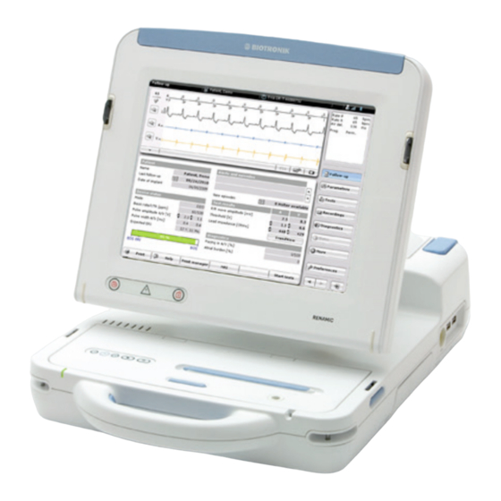
General description Renamic is a portable programmer and monitoring device that can be custom- equipped with a UMTS module. It is used during the implantation procedure and follow-up of BIOTRONIK implant- able pacemakers, ICDs (implantable cardioverter-defibrillators), or implantable cardiac monitors. - Page 4 Introduction Target group This technical manual is intended for physicians and trained medical personnel who are familiar with the following: • The use of implantable pacemakers, ICDs, and implantable cardiac monitors • The risks and possible complications associated of using these systems Additional requirements include: •...
-
Page 5: Safety During Use
Safety during Use Safety during Use Safety during Use2377213Technical ManualRenamic Intended Medical Use Intended medical use The Renamic programmer provides communication with the implantable pace- maker, ICD, or implantable cardiac monitor during the implantation procedure or follow-ups. The Renamic programmer is intended to be used for the following tasks: •... -
Page 6: Residual Risk
In addition, the BIOTRONK directives must be adhered to. Changes not permitted Only the manufacturer or a party expressly authorized by BIOTRONIK is allowed to perform corrective maintenance, enhancements or modifications to the device, except for the enhancement of modules. -
Page 7: Operating Conditions
Operating Conditions Transport and storage • If the packaging is damaged, please contact BIOTRONIK immediately. Do not put the device into operation. CAUTION Functional impairment due to external damage Mechanical impact, for example dropping the unit - even from a height of over 5 cm if unpackaged - can permanently impair the function of the system. - Page 8 • Only those power connection cables which are suitable for medical devices may be used, e.g. BIOTRONIK power cords (see Accessories, p. 37) or power cords of equal value labeled H05VV 3 x 0.75 mm, H05VV 3 x 1 mm or SJT AWG18.
-
Page 9: Electromagnetic Interference
If the interference continues, contact BIOTRONIK immediately. Note: If accessories other than those specified by BIOTRONIK are used, increased interference or lower resistance to interference can be expected. Note: If accessories specified by BIOTRONIK are used on other devices, increased interference or lower resistance to interference can be expected. -
Page 10: Maintenance, Care And Disposal
Safety during Use Maintenance, Care and Disposal The following regulations are valid for the device. WARNING Exposure to fluids may result in fatal injury Before cleaning and disinfecting device surfaces: Pull the power plug! CAUTION Danger of explosion if exposed to cleaning and disinfecting agents Let cleaning and disinfection agents evaporate before operating the device. - Page 11 WEEE directive had been enforced locally. • Return devices that are no longer in use to BIOTRONIK. Disposal of cables Note: Cables to be disposed of due to contact with blood must be disposed of as medical waste, in accordance with environmental regulations.
-
Page 12: Startup
Startup Startup Startup3377213Technical ManualRenamic Device Overview Device in operating position Fig. 1: Device operating element in working position, viewed from the front right Explanation of items Explanation of the individual items: Item Designation / description Screen (touchscreen) Device body USB ports ECG port Slot for expansion module Screen release key (right) - Page 13 Startup Device in transport position Fig. 2: Device operating element in transport position, viewed from the front left Explanation of items Explanation of the individual items: Item Designation / description Carrying handle Fixation for carrying strap (left) Screen release key (left) Paper tray for internal printer On/off key Power cord port and device fuse...
- Page 14 Startup PGH compartment Fig. 3: Device operating elements, PGH compartment with lid open, viewed from above/in front Explanation of items Explanation of the individual items: Item Designation / description PGH port USB slot for Bluetooth USB adapter PGH cable and ECG cable Cable feedthrough for PGH cable On/off light indicator Programming head (PGH)
- Page 15 Startup Power cord storage compartment Fig. 4: Device operating elements, power cord storage compartment with lid open, viewed from above/behind Explanation of items Explanation of the individual items: Item Designation / description Anti-slip stand Gripping tab Power cord in power cord storage compartment Power cord compartment lid...
-
Page 16: Transportation And Setup
Startup Transportation and Setup Transporting the device • Renamic has an integrated ergonomic handle in the front and a gripping tab in the back, which can be used to safely transport the device in any position. • A carrying strap can also be attached to the device. •... - Page 17 Startup Tilting the screen up • In transport position (screen closed), unlock the screen by pressing both release keys at the same time. You can hear and feel the device unlock. • Hold the sides of the screen with both hands and tilt it up to the position you would like to use it in (1).
-
Page 18: Connections And Cables
Startup Connections and Cables Basic notes for cables and Note: Do not force the plugs into the ports. When disconnecting plugs, do not pull connections on the cable. Note: Only connect external devices that conform to DIN EN 60601 or DIN EN 60950 standards. - Page 19 Startup WARNING Danger to patient from allergic reactions If the cable comes into contact with open wounds, it can cause allergic reactions. • Prevent the cable from coming into contact with open wounds. WARNING Danger from loss of function Damp cables have limited functionality and pose a danger to patients. •...
- Page 20 Startup The ECG port is located on the back right of the device. Fig. 7: Position of the ECG port • Connect the ECG cable to the ECG port. Note: Cables to be disposed of due to contact with blood must be disposed of as medical waste, in accordance with environmental regulations.
- Page 21 Note: The Bluetooth adapter used for data transfer must support the Microsoft Bluetooth standard. BIOTRONIK supplies a compatible Bluetooth adapter with the programmer. • Before using the Bluetooth adapter, ensure that it is authorized for Bluetooth radio communication in your respective country / region.
-
Page 22: Power Supply
Startup Power Supply Power supply The device is operated via the AC voltage of a room used for medical purposes: • 100 – 115 V ±10% / 60 Hz / 1.2 A / AC • 220 – 230 V ±10% / 50 Hz / 0.6 A / AC Connecting the power cord The connection for the power supply is located on the back of the device on the left. - Page 23 Startup Ready-for-service status, After successful booting of the operating system, the screen displays the complete start screen start screen which indicates the device's ready-for-service status. Depending on whether a programming head is connected, the device has telemetry contact to an active implanted device and/or which other ports are occupied, then the start screen may display additional details.
-
Page 24: Using Renamic
Using Renamic Using Renamic Using Renamic4377213Technical ManualRenamic Keys, Displays and Signals Keys on the device The device has several keys to which fixed functions are assigned. Overview of the device keys: Designation Description Emergency keys • Safe program key to switch on the safe program of the implanted device (emergency pacing). - Page 25 Using Renamic The printer keys are located on the left side of the PGH compartment lid. Fig. 13: Location of the printer keys On/off light indicator The on/off light indicator shows whether the device is switched on (lit) or off (not lit). It is located on the front left edge of the device.
-
Page 26: Emergency Programs
Using Renamic Emergency Programs QUICK REFERENCE GUIDE SAFE PROGRAM (EMERGENCY PACING): FOR EMERGENCIES Step Action Establish telemetry contact. Press the safe program key: DELIVER EMERGENCY SHOCK: Step Action Establish telemetry contact. Press the emergency shock key: In the dialog window, select [EMERGENCY SHOCK]. Purpose of the emergency The emergency keys are used for the following: keys... - Page 27 Using Renamic Location of the emergency keys Fig. 14: Location of the emergency keys on the device Start emergency pacing Proceed as follows: Step Action Establish telemetry contact. Press the safe program key: Stop emergency pacing Proceed as follows: Step Action Activate the desired permanent parameters in the program of the implanted device and transfer them to the implanted device.
-
Page 28: Programming Head
Using Renamic Parameter values Table 1: Safe program default parameter values Parameter Value Mode Basic rate 70 ppm Pulse amplitude 7.5 V Pulse width 1.5 ms Table 2: Emergency shock default parameter values Parameter Value Shock waveform Biphasic Type DF (defibrillation shock) Energy Maximum energy of the respective ICD Programming Head... - Page 29 SafeSync RF telemetry establishes a wandless telemetry connection between the programmer and devices with the BIOTRONIK SafeSync function. The programmer and devices that offer the BIOTRONIK SafeSync function have a specific type of transmitter, with which high frequency radio transmission is possible. The estab- lishment of SafeSync RF telemetry depends on the device being used.
- Page 30 Using Renamic The LED at the front of the programming head shows its status: LED status (flashing) Status programming head Orange Not ready (toggling to 'telemetry via programming head' is only possible using the software) CAUTION Higher energy consumption SafeSync RF telemetry requires somewhat more power. Consumption during implantation corresponds to approximately 10 days of service time and consump- tion during a 20-minute follow-up corresponds to approximately 3 days.
-
Page 31: Communication With Active Implanted Devices
• The software is installed on the Renamic device drive by BIOTRONIK employees. • Software can only be updated on site by BIOTRONIK employees or by those authorized by BIOTRONIK. -
Page 32: Using The Internal Printer
Unusable printouts; printer damages The use of paper not intended for this device can lower the quality of the printout or cause damage to the device. • Use paper specified by BIOTRONIK at all times. See: Package contents, p. 37. Step Action To open the paper tray: •... - Page 33 Using Renamic Step Action To insert paper: • Press back the separating flap. • Pull back the first page of the paper block. • Place the block of paper in the tray from above so that the wide marking of the paper block is on the left side. •...
-
Page 34: Using An External Printer
Using Renamic Print The printer keys are located on the left front side. Fig. 19: Printer keys Key assignment from left to right: • You can use the numbered keys to switch on the printer with the respective printing speed in mm/s. •... -
Page 35: Ecg And Iegm Functions
Using Renamic ECG and IEGM Functions Connecting the ECG cables See section: Connect ECG cables, p. 17 ECG recorder and All ECGs can be displayed in real time in the recorder or trigger mode and printed ECG monitor on the internal printer. ECG leads Table 3: Accessories for ECG leads... -
Page 36: Appendix
Appendix Appendix Appendix5377213Technical ManualRenamic Technical Data Physical characteristics Category Design Dimensions (W x D x H) 345 x 476 x 125 mm Mass including power cord, ECG cable, 10.5 kg programming head and stylus Housing material PC/ABS General classification Category Design Classification AIMD according to Directive 90/385/EEC... - Page 37 Appendix Programming head Category Design Applied part classification Dimensions (W x D x H) 97 x 145 x 42 mm Weight 0.5 kg PGH cable 2.9 m Degree of protection IP 30 Magnetic flux density Max. 3 mT Interface Redel plug, 14-pole Power cord port Category Design...
-
Page 38: Package Contents And Accessories
Appendix UMTS module Category Design Model Type 4 band GSM +3 band UMTS UMTS frequencies 850 MHz, 1900 MHz, 2100 MHz GSM frequencies 850 MHz, 900 MHz, 1800 MHz, 1900 MHz Max. UMTS power of transmission 0.25 W Max. GSM power of transmission 2 W: 850/900 MHz 1 W: 1800/1900 MHz Max. - Page 39 Appendix Item designation Description Order no. NK-11 (3 m) Power cord US 128865 NK-16-GB (2 m) Power cord for the United Kingdom 330705 NK-19-CN (2.5 m) Power cord for China 339034 NK-21-AU,UY (2.5 m) Power cord for Australia and Uruguay 339035 NK-22-AR (2.5 m) Power cord for Argentina...
-
Page 40: Electromagnetic Compatibility In Compliance With En 60601-1-2:2007
Appendix Electromagnetic Compatibility in Compliance with EN 60601-1-2:2007 • As the user, you must ensure that the device is operated in a suitable electro- magnetic environment. • The following guidelines may not be applicable in all cases. The propagation of electromagnetic values is, for example, affected by the absorption and reflection of structures, objects and people. - Page 41 Appendix Resistance to electro- • When the measured field strength exceeds the specified compliance level at the magnetic interference operating location of the Renamic device, observe the device in order to (tables 2 and 4) determine whether it is functioning properly. •...
-
Page 42: Country-Related Information
Appendix Country-Related Information UL certification Renamic has been certified by Underwriters Laboratories Inc. with respect to elec- trical shock, fire and mechanical hazards only in accordance with: • UL 60601-1 • CAN/CSA C22.2 No. 601.1 • IEC 60601-1: 1988 + A1 + A2 UL-certified devices are identified as follows: Medical Electrical Equipment UL 60601-1... -
Page 43: Symbols On The Components
Appendix Symbols on the Components Symbols on the right side of The symbols mean the following: the device ECG port with applied part classification BF, defibrilla- tion-proof USB ports Binary interface (slot for expansion module) Follow the instructions in the technical manual! Symbols on the left side of The symbols mean the following: the device... - Page 44 European Directive 2012/19/EU regarding waste electrical and electronic equipment (WEEE) applies. Return devices that are no longer used to BIOTRONIK. European approval mark IP30 • Protection against the ingress of solid foreign bodies with a diameter of 2.5 mm or more...
-
Page 45: Legend For The Label
Device contains materials that must be correctly disposed of in accordance with environmental protec- tion regulations. European Directive 2012/19/EU regarding waste elec- trical and electronic equipment (WEEE) applies. Return devices that are no longer used to BIOTRONIK. - Page 46 Appendix Programmer (Renamic) for electro-therapeutical implantable devices Cable and adapter Programming head Magnetic field warning sign...
-
Page 47: Directories
Directories Directories Directories6377213Technical ManualRenamic List of Keywords Characteristics, 35 Cleaning, 9 Connect external devices ECG cable, 17 Programming head, 17 Connection of external devices Bluetooth adapter, 20 USB devices, 19 Connection of external devices, external printer, 33 Damage, 6 Defibrillation, 6 Device key Emergency pacing, 25 Emergency shock, 25... - Page 48 Directories Package contents and accessories, 37 Patient environment, 7 Power Supply, 21 Printer External, 33 Internal, 31 Programming head, 27 Recommended safety distances, 39 Resistance to electromagnetic interference, 40 Risks, 5 Safe program Key on the programming head, 29 Parameter values, 27 Safety warnings, summary, 5 Set-up location, 6 Software, 30...
- Page 49 © BIOTRONIK SE & Co. KG All rights reserved. Specifications subject to modification, revision, and improvement. 0123 Distributor: Manufacturer: 2010 BIOTRONIK, Inc. BIOTRONIK SE & Co. KG 6024 Jean Road Woermannkehre 1 Revision: I (2017-03-07) Lake Oswego, 12359 Berlin · Germany...
Need help?
Do you have a question about the Renamic H24 and is the answer not in the manual?
Questions and answers