
Subscribe to Our Youtube Channel
Related Manuals for Lorentz PSk3-7


Summary of Contents for Lorentz PSk3-7
- Page 1 PSk3-7 to PSk3-15 Hybrid Solar Pumping System Manual for Installation and Operation Manual for Installation and Operation Manuel d'installation et d'utilisation Manual de instalación y operación The Solar Water Pumping Company...
-
Page 2: Table Of Contents
LORENTZ Assistant ........92... -
Page 3: Introduction
1 Introduction 2 Installation overview Thank you for purchasing a LORENTZ pump system. With PSk3, LORENTZ has set a new standard for This installation overview is provided to familiarize you with the typical steps that are taken when installing a quality, efficiency and durability in solar pumping. -
Page 4: Registration Of Components
PV array to +, the negative terminal to −. The Installation“ on page 49 and "Table 2: Technical Sites in partnerNET (Support, Sites) or by using the LORENTZ Assistant App. This is mandatory and needs to max. input voltage provided by the PV array must Data of the PSk3 Controller"... -
Page 5: Feature Configuration With Lorentz Assistant
Installation overview Installation overview 2.5 Feature configuration with LORENTZ Assistant 3. Operational settings: if required choose a time 4. Device info: check hardware and firmware 1. Installation settings: select your controller 2. Dashboard: check your pump’s performance in limit or a water limit (e.g. for a low-yielding borehole... -
Page 6: Psk3 And Lorentz Assistant
LORENTZ pump controllers via a where they reliably meet the most demanding the PV power source to meet the customers’... -
Page 7: Product Information
Additional information about pumps and motors can 460 V / 480 V is 50 ppm, for surface pumps 20 ppm. A higher sand be found in the LORENTZ COMPASS sizing software. Rated frequency 50 Hz content will reduce the pump life considerably due to wear. -
Page 8: Naming Convention
Prolonged intermediate storage in an environment LORENTZ pumps are supplied from the factory in centrifugal centrifugal surface of high humidity and fluctuating temperatures must proper packing in which they should remain until be avoided. Moisture condensation may damage they are to be installed at the site. -
Page 9: Safety Instructions
Safety Instructions Safety Instructions 5 Safety Instructions WARNING – The appliance is not to ƒ Dangers of ignoring the safety symbols – ƒ Safety directions for maintenance, inspection be used by persons (including children) Ignoring the safety directions and symbols and assembly work –... -
Page 10: Pump System Sizing & Layout Diagrams
Incorrect parameters the manufacturer. There are no user-serviceable system, various variables need to be taken into available for download to all LORENTZ partners on can lead to a wrong sizing report. parts inside the motor or the controller. -
Page 11: System Layout: Submersible Pumps
Pump System Sizing & Layout Diagrams Pump System Sizing & Layout Diagrams 6.2 System Layout: Submersible Pumps 6.3 System Layout: Surface Pumps CAUTION CAUTION – This graphic is an – This graphic is an example example pump system layout diagram pump system layout diagram and for and for ease of understanding only. -
Page 12: Solar-Diesel System Sizing Considerations
The constant power rating of the diesel generator should be selected considering the desired flow or pressure. LORENTZ SmartSolution supports the following diesel generator specifications: ƒ 380/ 400/ 415/ 440/ 460 /480 V ƒ 50/ 60 Hz ƒ Remote start function (if use of SmartStart is... -
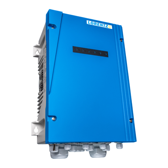
Page 13: Controller Installation
Dry running will damage the pump it is shaded from the midday sun. An ideal location and void the warranty. LORENTZ requires is in permanent shade. If no shade is available, cut a dry run protection for every pump a piece of sheet metal and bolt it behind the top of system. -
Page 14: Mounting, Space And Ventilation Requirements
Controller Installation Controller Installation 7.3 Mounting, Space and Ventilation Figure 4: PSk3 controller dimensions for installation Figure 5: Minimum spacing for wall mounting Requirements The PSk3 controller must be mounted on a solid wall or a rigid structure. The installation plane must be concrete, metal, stone or any other material with similar properties that 50 mm/2”... -
Page 15: Wiring The Controller
– Do not connect any electrical load to terminals contain strong springs. Refer to „Figure 8: disconnection to avoid electric shock the PV generator other than the LORENTZ Spring connector for "Solar-IN" and "Motor-OUT"“ hazard. pump controller. Connection of a battery on page 31. - Page 16 Controller Installation Controller Installation sensor terminals 255-40* Terminal description PSk3 Figure 7: Sensor terminal wiring example Figure 8: Spring connector for "Solar-IN" and "Motor- Figure 9: Spring connector for "Sensor terminals 1-18 OUT" and fan terminal" Well Remote Water Analog 1 Analog 2 Water Relay...
- Page 17 Controller Installation Figure 10: PSk3 sensor terminals Potential-free signal output to control connect to NC third party devices; must be configured with LORENTZ Assistant; either NC or NO connect to COM Relay operation can be used Maximum switching capability remote...
- Page 18 ƒ the switch must be rated for DC current, NOT AC The motor phases are labeled with "U", "V", "W". Solar input cable Motor Out cable gland gland A PV disconnect switch that matches all these requirements can be purchased from LORENTZ.
- Page 19 Controller Installation Controller Installation Figure 12: Example configuration of different components CAUTION NOTE – The wiring order will have – Always subtract this impact on the motor rotation direction. value from your motor resistance The correct rotation direction is marked measurements! with an arrow sticker on the pump and motor.
- Page 20 For motor cables, the minimum wire size depends on Calculation of expected phase-to-phase the system size and sizing. Compare your wire sizes resistance: to the LORENTZ COMPASS sizing reports. Cables should be shielded to meet EMC requirement. = 1.4 Ω + 2 × 150 m × 0.25 Ω / 100 m = 1.4 Ω + 2 × 0.375 Ω...
- Page 21 20 mA. an ageing effect on motor winding insulation. To a dry run protection for every pump impedance of 100 Ω can be connected, e.g. LORENTZ mitigate this effect, it is common to use a filter system.
- Page 22 These settings can only be power supply! Before any installation, connected together, which means always both the maximum current value compared to pure done via LORENTZ Assistant. (Please check LORENTZ maintenance or inspection activities wait power sources must be safely disconnected during sinusoidal currents.
- Page 23 PSk3 is monitoring the voltage range of the grid and – If the controller is used in “gR” or “gS” are recommended. For PSk3-7 the rated connects if the grid voltage is in range. hybrid operation the solar array must not...
-
Page 24: Grounding
Controller Installation Controller Installation Figure 14: Controller grounding 7.4.2.7 Further considerations The grounding is also important to the system As AC source and solar are coupled galvanically to for lightning protection. In general it is meant for each other it is important to always disconnect both indirect lightning strikes and induced electrical sources if installation or maintenance has to be done potentials during operation of the pump system. -
Page 25: Pump Installation
8 Pump Installation Figure 15: Grounding cable mounting at controller housing 8.1 General instructions 8.1.1 Pipe sizing bolt for LORENTZ pump systems are extremely efficient. It WARNING ground connection – All electrical connections is important to keep this efficiency throughout the... -
Page 26: Submersible Pumps
Pump Installation Pump Installation 8.2 Submersible Pumps For surface pumps: 8.1.2 Cable Splicing To connect the motor cable with a cable extension you should connect the cable ends with a splicing kit. Figure 17: Prevent air locks in pipes 8.2.1 System Layout: Submersible Pumps It is very important that the cable joints are fully sealed otherwise moisture could cause a short CAUTION... - Page 27 2 and 4. to consider the resistance of the multimeter leads drainage screws to allow water to exit from the and void the warranty. LORENTZ requires The wiring with the better flow rate has the right when measuring very low values: drainage hole.
- Page 28 0.25 Ω / 100 m [Ω] the resistance of phase-to-phase: 1-2, 2-3, 3-1. Calculation of expected phase-to-phase AC Drive Sub 6" 5.5 kW PSk3-7 Make sure there is good contact between the resistance: probes and the cable. AC Drive Sub 6" 11 kW PSk3-15 = 1.8 Ω...
- Page 29 40 m / 130 ft along the riser pipe. This will keep LORENTZ prescribes a dry run protection Table 11: Additional weight per meter pipe length any tensile forces away from the motor cable.
- Page 30 Pump Installation Pump Installation CAUTION 8.2.7 Installation – When you fit the pipe into Figure 27: Connection pump end with motor To connect the pump end and the motor you have The thread on the first section of the riser pipe the pump hold the pump only at the top to set the motor with the clamps in the borehole which is to be screwed into the pump should not be...
- Page 31 Pump Installation Pump Installation CAUTION – Impact between the pump Figure 28: Dismantling the lower clamp Figure 29: Connecting the next piece of pipe Figure 30: Dismantling the lower clamp end and motor can damage the pump system. CAUTION – The NEMA coupling of the motor and the pump end must be CLEAN when the pump end is mounted onto the motor.
-
Page 32: Surface Pumps
8.2.9 Additional Features 8.2.9.3 Flow sleeve A higher content will cause excessive wear within the All LORENTZ PSk3 submersible pumps are designed pump and reduce the pump’s life span considerably. 8.2.9.1 Safety Rope for the use of water with a temperature between 0°C... - Page 33 The motor phases are labeled with "U", "V", "W". CAUTION – The wiring order will have impact on the motor rotation direction. The correct rotation direction is marked with an arrow sticker on the pump and motor. Figure 32: Example LORENTZ PSk3 surface pumps...
- Page 34 [Ω] cable, the values of the table "Table 13: Motor cable resistance" and "Table 14: Motor cable AC DRIVE CS-F 5.5 kW PSk3-7 resistances for surface pump motors" on page AC DRIVE CS-F 7.5 kW PSk3-9 67, can be used as a rough approximation.
- Page 35 Please refer to COMPASS and the Handling – When lifting the CS-F pump use the must be mounted to the pump housing corresponding LORENTZ knowledge base article for eyebolts at the motor housing. CS-G pumps must be free of tension.
-
Page 36: Pump Accessories Installation
Dry running will damage the pump WARNING – Make sure that the and void the warranty. LORENTZ requires the pump and suction pipes are completely filled installed shutoff valves in the suction and with water, the voltage of the power supply is correct... -
Page 37: Water Detection Sensor
The purpose of the water detection the pump. (This may not be feasible if the well the terminals as shown on the diagram. For PSk3-7 casing is smaller than 6 in) sensor is to sense the loss of water and CAUTION to PSk3-15 please refer to "Figure 7: Sensor terminal... - Page 38 G1" of the pipe. Both stainless steel and steel adaptors water quality. 1.5x45° surfaces 17 ± 0.1 are available from LORENTZ. 35 ± 0.1 Rz 12.5 Step 2: Connect the sensor housing to the PTFE edges without 2 ± 0.1 washer on top of the adapter ("Figure 41: Mounted...
-
Page 39: Water Meter Installation
„Figure 43: HDPE pipe tee-piece“ on page 76. For information on the water meter installation, The LORENTZ range of liquid level sensors use The tee-piece must have a 1” female thread (G1”, please refer to the manual of the manufacturer. Pay pressure to measure the level of water in a well whitworth pipe thread). -
Page 40: Pressure Sensor Installation
(4) If it must run a long distance, use twisted-pair shielded cable to reduce the chance of damage ƒ For the pump types LORENTZ PSk3 CS-F1 to Float switch requirements: from lightning-induced surge. CS-F20 it is necessary to remove the vent plug to install the pressure sensor. -
Page 41: Sacrifical Anode
Wiring to the controller – The float switch will be Figure 53: PV Combiner 1000-125-4 Figure 54: PV Disconnect 1000-40-5 connected to the remote switch input. For PSk3-7 to PSk3-15 refer to "Figure 7: Sensor terminal wiring The LORENTZ Sacrificial Anode is designed for use example"... -
Page 42: Pv Protect 1000-125 For Psk3-7 To Psk3-15
Pump Accessories Installation Pump Accessories Installation 9.10 PV Combiner 1000-125-4 for PSk3-7 to 9.11 PV Protect 1000-125 for PSk3-7 to 9.12 SmartStart PSk3-15 PSk3-15 The LORENTZ PV Combiner is a PV connection The LORENTZ PV Protect is a surge protective 9.12.1 Product description... - Page 43 The battery and connections These terminals are marked NO and Com ("Figure 56: If the battery is not delivered by LORENTZ, it must are accessible from the front after removing the Opened SmartStart" on page 85). The connector meet the following characteristics: screwed lid.
-
Page 44: Operating The Pump
Pump Accessories Installation Operating the Pump 10 Operating the Pump Wiring 9.12.7 LED status The wiring must be done by qualified staff only. In the kit there is a green 2-pin plug with two pre- A flashing red LED indicates that the battery voltage This graphic displays the front LED indicators of the The on/off switch is located at the bottom of the assembled cables (black and red). - Page 45 Flashing indicates the pump is not running due automatically speed up or restart after cooling switch in OFF position flashing to settings, e.g. a timer set up with LORENTZ down. Assistant. no light Insufficient power input ƒ Source low (red) – The water source has ƒ Pump (green) –...
-
Page 46: Starting The Pump
ON. The pump should now start immediately if sufficient power is present. Detailed instructions on how to use the app and what configurations have to be made are can be found in the app itself and also on LORENTZ partnerNET. WARNING – A missing or wrong... -
Page 47: Lorentz Connected
PSk3 system. Users can log on at anytime via gateway to communicate via Bluetooth® with the a web browser to see all of their LORENTZ pump PSk3 controller and the cloud based LORENTZ systems in an intuitive management interface. -
Page 48: Troubleshooting
Should technical support the pump. The pump will start to turn or only vibrate often damaged by animals if they are not enclosed by LORENTZ become necessary, please provide the (2) After full-tank float switch resets – 2 to 3 a little. -
Page 49: Service And Maintenance
The cooling fan and heat sink can collect dust and (2) there no speed limitation set in LORENTZ If a DC power source (PV Generator) particles over time. They should be inspected Force a quick start Assistant. - Page 50 1. temperature, humidity 1. temperature < 50 °C environment 2. dust, gas 2. humidity < 80 %, no dew condensation, no peculiar smell, flammable, explosive gas BERNT LORENTZ GMBH cooling system 1. installation 1. excellent ventilation in installation Siebenstuecken 24 environment...
Need help?
Do you have a question about the PSk3-7 and is the answer not in the manual?
Questions and answers
How can I adjust the frequency of the inverter