Table of Contents
Advertisement
Quick Links
0410001000101EV10-00 0410001000202EV10-00 0410001001111EV10-00
0410001001212EV10-00 0410001001313EV10-00 0410001003131EV10-00
0410001003333EV10-00 0410001003637EV10-00 0410001003535EV10-00
0410001005151EV10-00 0410001005353EV10-00 0410001005657EV10-00
0410001005555EV10-00
System
e-light
2M
6x10/100TX und 2x100FX
Managed Industrial Ethernet Switch
Version: EN_Manual_e-light-2M_v2.8.doc
Description and Manual
eks Engel GmbH & Co. KG
Schützenstraße 2-4
DE-57482 Wenden-Hillmicke
Tel:
+49 (0) 2762 93136
Fax:
+49 (0) 2762 9313-7906
E-Mail:
info@eks-engel.de
Internet:
www.eks-engel.de
Advertisement
Table of Contents

Related Manuals for eks e-light 2M


Summary of Contents for eks e-light 2M
- Page 1 0410001005151EV10-00 0410001005353EV10-00 0410001005657EV10-00 0410001005555EV10-00 System e-light 6x10/100TX und 2x100FX Managed Industrial Ethernet Switch Version: EN_Manual_e-light-2M_v2.8.doc Description and Manual eks Engel GmbH & Co. KG Schützenstraße 2-4 DE-57482 Wenden-Hillmicke Tel: +49 (0) 2762 93136 Fax: +49 (0) 2762 9313-7906 E-Mail: info@eks-engel.de Internet: www.eks-engel.de...
-
Page 2: Table Of Contents
Content Introduction ..............1 Characteristics ............1 Packing content ............2 View of front panel ............ 3 Reset-button ............. 4 DIP-switch ..............4 LED Indications ............6 Ports ................. 8 Cabling ..............10 Connecting the differential relay ......12 Mounting on DIN rail ..........13 Ports and dimensions .......... - Page 3 Preparations ............20 System Login ............20 Port Status .............. 22 Single Port Information ........... 22 Port Statistics ............24 Port Control ............25 Switch Settings ............26 Port Mirroring ............27 VLAN Configuration ..........28 Port-Based VLAN ............29 802.1Q VLAN ..............
- Page 4 Per Port Configuration ............ 45 P-Ring ..............46 QoS Configuration ..........48 IGMP ..............51 Security Manager ........... 52 SNMP Configuration ..........53 Community Strings ............54 Trap Manager ..............55 Configuration Backup ..........55 TFTP Restore Configuration ........... 55 TFTP Backup Configuration ..........
- Page 5 Technical details ............64...
-
Page 6: Introduction
Introduction e-Light 2M is a managed 6x10/100TX plus 2x100FX Industrial ring switch especially designed for industrial applications. A Web GUI allows the very easy management of e-light 2M. Characteristics According to IEEE 802.3 10Base-T, 802.3u 100Base-TX/100Base-FX 6x10/100TX (RJ45) and 2x100FX (POF, HCS, MM or SM) -
Page 7: Packing Content
Packing content Please compare the packings content with the list below: e-light 2M Ring Managed Industrial Switch Manual : EN_M -2M_ 2.8. TAND ANUAL LIGHT Ä ECHNISCHE NDERUNGEN VORBEHALTEN UBJECT TO ECHNICAL LTERATIONS EITE... -
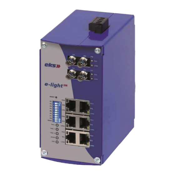
Page 8: View Of Front Panel
Hardware description This section contains information about the hardware ,the ports, the cabling and the installation of e-light 2M. View of front panel Front panel of e-Light 2M : EN_M -2M_ 2.8. TAND ANUAL LIGHT Ä ECHNISCHE NDERUNGEN VORBEHALTEN UBJECT TO... -
Page 9: Reset-Button
Reset-button With the reset button the switch can fast and easily be reset and restarted and the configuration can be reset to the default value. Restart: Keep the button pressed for 2 seconds. Reset to default value: Keep the button pressed for 5 seconds. - Page 10 Alarm of port 3 switched off. Alarm of port 3 active. If the port’s link fails, the fault LED lights up. Alarm of port 4 switched off. Alarm of port 4 active. If the port’s link fails, the fault LED lights up. Alarm of port 5 switched off.
-
Page 11: Led Indications
Function ring master switched off. Function „switch as ring master in ring group“ active. [Note] If the function „port alarm“ is active, the LED flashes and the alarm relay signals port errors. Please restart the switch after having set the DIP-switch. LED Indications The front panel of the switch contains 5 diagnostic LEDs which offer real time information on the system. - Page 12 Green Power input at VDC 2 VDC 2 No power input at VDC 2 Voltage breakdown, RJ45-port error Yellow or fiber optic port error Fail No voltage breakdown, RJ45-port error or fiber optic port error The switch is the master of the ring Green group.
-
Page 13: Ports
Assignment [Note] “+” and “-” signs represent the polarity of each wire pair. All TX-ports of the e-light 2M support the automatic MDI/MDIX operation.Direct cabling can be used for all network connections to PCs, servers, other switches or hubs. In direct cablings the pins 1, 2, 3 and 6 at one end of the cable are directly connected to the pins 1, 2, 3 and 6 at the other end of the cable. - Page 14 Pin MDI-X Signal Name MDI Signal Name Receive Data plus (RD+) Transmit Data plus (TD+) Receive Data minus (RD-) Transmit Data minus (TD-) Transmit Data plus (TD+) Receive Data plus (RD+) Transmit Data minus (TD-) Receive Data minus (RD-) Direct cabling Cross-over cabling Fiber optic port There are two 100Base-FX ports which are suitable for multimode (2km) and/or...
-
Page 15: Cabling
Please refer to the scheme below when cabling two fiber optic ports. False cabling may lead to the port not working properly. Attention Do not look into the laser or the LED! Cabling Please use twisted-pair cables of the category 5 or higher to connect the RJ45 port. - Page 16 Wiring the power supply Please connect the power supply to the clamps VDC1 and GND. The redundant power supply shall be connected to VDC2 and GND. The terminal block for the power supply is stackable and can be locked with two screws.
-
Page 17: Connecting The Differential Relay
Connecting the differential relay There is a potential free differential relay contact (semiconductor relay) at the clamps K1 to K4; K1 and K3 are the common connectors of the relay. If a voltage breakdown, a RJ45-port error or a fiber optic port error is detected, the differential relay drops down (K1-K2 closed and K3-K4 opened). -
Page 18: Mounting On Din Rail
Mounting on DIN rail As standard, e-light 2M has got a clip for 35mm DIN rails according to DIN EN 60175. For mounting the system please engage it onto the rail at the bottom side (see left picture), press it against the spring force to the top (1) and then towards the mounting plate (2). -
Page 19: Ports And Dimensions
Ports and dimensions The following view shows the ports and the dimensions of the e-light 2M switch: : EN_M -2M_ 2.8. TAND ANUAL LIGHT Ä ECHNISCHE NDERUNGEN VORBEHALTEN UBJECT TO ECHNICAL LTERATIONS EITE... -
Page 20: Hardware Installation
Hardware Installation This paragraph describes how to install the e-light 2M switch: Procedure: 1. Unpack the switch. 2. Switch the device on. Tips regarding wiring can be found in the paragraph wiring the power supply. The power LED lights up. Its meaning can be found in the paragraph LED indications.
Need help?
Do you have a question about the e-light 2M and is the answer not in the manual?
Questions and answers