Advertisement
INSTALLATION INSTRUCTIONS
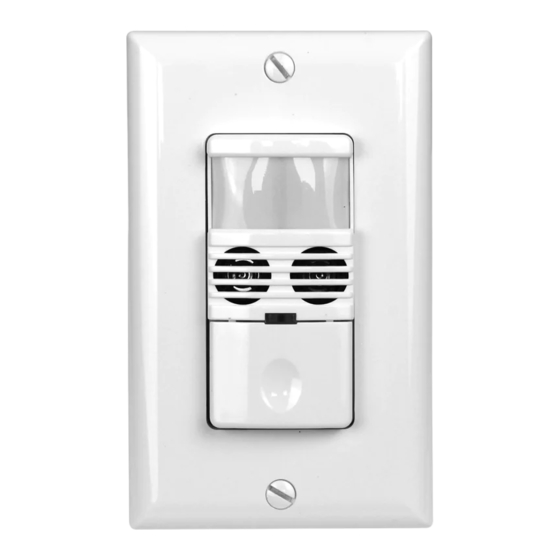
SC-SWSDU-W
Multi-Technology PIR/Ultrasonic
Single Relay Pole Wall Sensor Switch
NEUTRAL REQUIRED
SC-SWSDU-W
SPECIFICATIONS
Voltage ................................................................ 120/277VAC,50/60Hz
Load Requirements:
Incandescent .................................. 800W-120VAC,50/60Hz
Fluorescent ....... 800VA-120VAC,1600VA-277VAC,50/60Hz
Motor ................................................1/4HP-120VAC,50/60Hz
Adjustment Time Delay ............................................... 15Sec to 30Mins
Walk-Through Mode ..................... 3 minutes if no activity after 30 sec.
Test Mode ..................... 15 sec. at initial power up or DIP switch reset
PIR Adjustment ............................................. High or Low (DIP switch)
Ultrasonic Adjustment .........................
Minimum to Maximum (trimpot)
Light Level Adjustment ............................... 100 Lux --daylight(trimpot)
Operation Temperature .................................................... 32° F--131°F
DESCRIPTION
The SC Series wall switch sensor provides a simple and cost-effective
standalone solution which utilizes dual technology PIR (Passive
Infrared) and Ultrasonic to turn lights ON and OFF based on occupan-
cy/vacancy. The vandal resistant lens provides major and minor
movement detection coverage with a 180° field-of-view sensor. The
sensor wall switch can be used to meet many of the Title 20/24,
ASHRAE 90.1, and IECC code requirements.
COVERAGE PATTERN
TOP VIEW
20'
10'
10'
PIR Coverage: 1200 ft
20'
Ultrasonic Coverage: 400 ft
SIDE VIEW
5'
4'
40'
20'
- 01-
WARNING:
INSTALLATION
Occupancy/Vacancy
(2-IN-1)
1. Make sure that the power has been turned OFF at the circuit
breaker.
2. Connect lead wires according to wiring diagram (see Figure 2.)
Black lead to Line(Hot), Red lead to Load wire, White lead to
Neutral wire, Green lead to Ground.
Wiring Diagram:
3. Mount device "TOP" up.
4. Gently position wires in wall box, attach sensor switch to the box.
5. Restore power at circuit breaker or fuse, wait one minute.
6. Remove the small cover plate. (see Figure 3.)
7. Locate the adjustment trimpots on the control panel to perform
test and adjustment. (see Figure 3 and 4.)
8. Replace the small cover plate after testing and adjustment.
2
2
Figure 1
Turn off the circuit breaker before installation.
Indoor use only.
Do not exceed electrical ratings.
Neutral
White
Hot
Load
Load
Black
Red
Ground
Neutral
Green
White
Figure 2
Figure 3
-02-
ADJUSTMENT
PIR Lens
Control Panel Cover
ON
2
3
1
4
1 2 3 4 5 6 7
ULTRASONIC
2
3
OFF
1
4
LIGHT
OFF OCC VAC
OFF OCC VAC
Figure 4
Switch Position:
Position
Mode
Description
(OFF)
Circuit is permanently open. Switch disabled.
Left
Load will not react to the push button.
Off Mode
Occupancy Mode:
Automatic ON/OFF, time delay programmed
(OCC)
with Time Delay dipswitch setting (15 seconds -
Center
Occupancy
30 minutes). See Time Delay table setting below
Vacancy Mode:
Manual ON/ Automatic OFF, time delay programmed
(VAC)
Right
with Time Delay dipswitch setting (15 seconds -
Vacancy
30 minutes). See Time Delay table setting below
Ultrasonic Sensitivity Adjustment Trimpot
Default position: Center at 65%
Adjustable: 30% (Position 1) to 100% (Position 4)
Note: Turn toward right for greater room space.
Turn toward left to avoid false alert in smaller room and near
the door way or heat source.
Ambient Light Level Adjustment Trimpot
Default position: Daylight (100% at position 4)
Adjustable: Daylight to 100Lux (Counter clockwise)
-03-
Mounting Yoke
Ultrasonic Cones
Detection LEDs
Red=PIR
Blue=Ultrasonic
ULTRASONIC
LIGHT
Advertisement
Table of Contents

Related Manuals for MaxLite SC-SWSDU-W

Summary of Contents for MaxLite SC-SWSDU-W
- Page 1 INSTALLATION INSTRUCTIONS SC-SWSDU-W ADJUSTMENT WARNING: Turn off the circuit breaker before installation. Indoor use only. Mounting Yoke Multi-Technology PIR/Ultrasonic Do not exceed electrical ratings. PIR Lens Single Relay Pole Wall Sensor Switch INSTALLATION Occupancy/Vacancy Control Panel Cover (2-IN-1) Ultrasonic Cones 1.
- Page 2 The Load does not turn On without LED flashing or LED flashing regardless of motion: The SC-SWSDU-W has 7 DIP switches under the cover. They The SC-SWSDU-W is programmed independently for either are used to set sensitivity, time delay, trigger mode, walk through Occupancy Mode or Vacancy Mode as refer to the Band Switch 1.
Need help?
Do you have a question about the SC-SWSDU-W and is the answer not in the manual?
Questions and answers