Table of Contents
Advertisement
Quick Links
Advertisement
Table of Contents

Summary of Contents for UTC interlogix NX-8V2
- Page 1 NX-8V2 Control Panel Installation Manual P/N I-NX8V2-IM • REV H • ISS NOV12...
- Page 2 US and international copyright law . Disclaim er The information in this document is subject to change w ithout notice. UTC Fire & Security assumes no responsibility f or inaccuracies or omissions and specifically disclaims any liabilities, losses, or risks, personal or otherw ise, incurred as a consequence, directly or indirectly, of the use or application of any of the contents of this document.
-
Page 3: Table Of Contents
Content Important information ii Chapter 1 Introduction 1 Product overview 2 Board installation 3 Wiring 3 Module list 6 Chapter 2 Programming 9 LED keypad programming 11 Control panel programming 14 Programming locations 19 Chapter 3 Troubleshooting 53 General diagnosis 54 Trouble conditions 54 Voltage tables 56 Specification 57... -
Page 4: Important Information
Important information This is the NX-8V2 Control Panel Installation Manual. This document includes an overview of the product and detailed instructions explaining how to install the NX- 8V2 board inside the enclosure and how to program the control panel. To use this document effectively, you should have the following minimum qualifications: •... -
Page 5: Introduction
Chapter 1 Introduction Summary This chapter provides an overview of your NX-8V2 Control Panel, including basic installation and terminal connections. Content Product overview 2 Product contents 2 Board installation 3 Wiring 3 Terminal descriptions 5 Module list 6 NX-8V2 Control Panel Installation Manual... -
Page 6: Product Overview
Chapter 1: Reporting codes Product overview The NX-8V2 Control Panel is a residential security and alarm system and provides the following features: • Sophisticated software allowing up to 99 users to interface with up to 48 zones and eight partitions. •... -
Page 7: Board Installation
Chapter 1: Reporting codes Board installation Inside the metal enclosure, there are slots for board insertions. These allow the PC board to be positioned vertically (Figure 2 below). When you slide the board between the grooves of the slots, make sure the terminal strip is toward the front opening (toward you) to allow for the wire connections. - Page 8 Chapter 1: Reporting codes Figure 3: NX-8V2 wiring diagram NX-8V2 Control Panel Installation Manual...
-
Page 9: Terminal Descriptions
Chapter 1: Reporting codes Terminal descriptions Table 2 below describes the terminals shown in the wiring diagram. Table 2: NX-8V2 terminals Terminal Description Not used Telephone ring (red wire on the standard RJ-31X cord) Telephone tip (green wire on the standard RJ-31X cord) Not used EARTH Earth ground. -
Page 10: Module List
Chapter 1: Reporting codes Module list Table 3 below shows some of the modules that are compatible with the NX-8V2 system. Additional information is available from customer support. Table 3: Module list Part number Description NX-8V2 NX-8V2 control only. NX-8V2-KIT NX-8V2 control, NX-108E LED keypad, 16.5 V 40 VA transformer. - Page 11 Chapter 1: Reporting codes Part number Description NX-1324E 24-zone LED door design keypad. NX-1448E 48-zone fixed language icon keypad. Note: The maximum number of zones available is 48 regardless of the devices added. Information regarding zone doubling is located in the Glossary. NX-8V2 Control Panel Installation Manual...
-
Page 13: Programming
Chapter 2 Programming Summary This chapter provides basic programming instructions and a description of the programming locations. Content LED keypad programming 11 Keypad options 11 Keypad number and partition 12 Elapsed increments 12 System date 12 System clock 13 User codes 13 User authority level 13 Control panel programming 14 Programming data types 16... - Page 14 Chapter 2: Reporting codes Location 44 - Duress code 37 Locations 45 to 50 - Auxiliary outputs programming 37 Location 51 - Autotest control 40 Locations 52 to 55 - Times and days 41 Locations 56 to 83 - 4+2 format communicator codes 42 Location 84 - Daylight saving time 44 Locations 88 to 109 - Partition account codes and features.
-
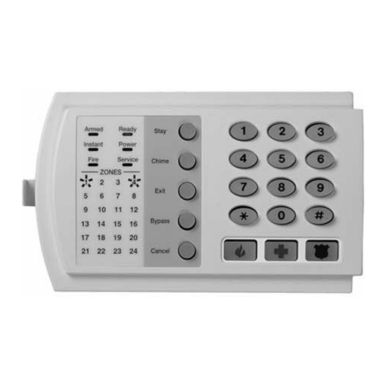
Page 15: Led Keypad Programming
Chapter 2: Reporting codes LED keypad programming This section describes how to program the address of each LED keypad, as well as the options that are available. The keypad must be addressed for control panel supervision of that keypad. Programming defaults include: •... - Page 16 Chapter 2: Reporting codes Keypad feature enabled Enable multiple partition viewing. Enable temporary viewing of all partitions by pressing *, 1, partition number. Keypad number and partition To set the keypad number and partition: 1. Enter *, 9, 4, program code. The Service LED and the Instant LED will flash. 2.
- Page 17 Chapter 2: Reporting codes System clock To set the system clock: 1. Enter *, 9, 7, master code. The Service LED begins flashing. 2. Enter the clock time (military time). Hour: 00 through 23, where 00 is midnight, 01 is 1:00 a.m., 23 is 11:00 p.m. Minutes: 00 to 59. For example, 3.25 a.m.
-
Page 18: Control Panel Programming
Chapter 2: Reporting codes assigned authority levels to all user numbers, or you can press # to exit assigning authority level programming. Table 5: LED features Attributes if LED 8 is off Attributes if LED 8 is on Reserved Activate output 1 Armed only Activate output 2 Arm only after close window... - Page 19 Chapter 2: Reporting codes To enter program mode: 1. Press *, 8. The five function LEDs (Stay, Chime, Exit, Bypass, and Cancel) begin flashing. 2. Enter the go to program code (default 9, 7, 1, 3). If the go to program code entry is valid, the Service LED flashes, and the five function LEDs illuminate.
- Page 20 Chapter 2: Reporting codes You are now ready to enter another programming location. If you attempt to program and invalid entry for a particular segment, the keypad beeps three times indicating an error and remains in that segment awaiting a valid entry. To exit program mode: 1.
Need help?
Do you have a question about the interlogix NX-8V2 and is the answer not in the manual?
Questions and answers