
Summary of Contents for Ultraflo 200 Series
- Page 1 INSTALLATION AND OPERATION MANUAL Electric Quarter‐Turn Actuators 200 SERIES 2013.01 ...
-
Page 2: Table Of Contents
200 Series Electric Actuator Ultraflo Corporation | 2013.01 INDEX OVERVIEW .............................. 1 IMPORTANT NOTICES .......................... 2 STANDARD MOUNTING .......................... 3 SPECIFICATION ............................ 4 STORAGE INFORMATION ........................ 6 LUBRICATION ............................ 6 INSTALLATION ............................ 7 WIRING DIAGRAM .......................... 8 ... - Page 3 200 Series Electric Actuator Ultraflo Corporation | 2013.01 210 ~ 212 110V AC 1‐Phase Modulating Controller , 50% duty cycle .............. 35 210 ~ 212 220V AC 1‐Phase Modulating Controller , 50% duty cycle .............. 36 202 ~ 212 110V, 220V AC 1‐Phase On‐Off Controller , Local Control Unit ............ 37 202 ~ 212 220V, 380V, 440V AC 3‐Phase On‐off Controller , Local Control Unit .......... 38 202 ~ 208 110V, 220V AC 1‐Phase Modulating Controller , Local Control Unit , 30% duty cycle ..... 39 202 ~ 208 110V, 220V AC 1‐Phase Modulating Controller , Local Control Unit , 75% duty cycle ..... 40 ...
-
Page 4: Overview
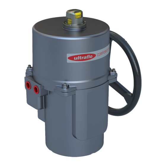
200 Series Electric Actuator Ultraflo Corporation | 2013.01 OVERVIEW Ultraflo electric quarter‐turn actuators offer a range of 443 lb.in(50Nm) to 30,991 lb.in(4500Nm) torque. Product design is based on a self‐locking worm drive principal, which provides for a smooth running, dependable, robust drive system. All models are ISO 5211 compliant, have a visual position indicator on top of actuator cover and manual override. The manual operation is a non‐clutch design that can be operated without any lever, clutch or brake upon power outage. Features 30% duty cycle at ambient temperature and rated torque. Self ‐ locking gearing. Built‐in thermal protection prevents motor burn out. AC motor is 125°C (257°F) and 90°C (194°F) for DC motor. (The 75% duty cycle actuator uses DC motor.) Max Torque Weight ... -
Page 5: Important Notices
200 Series Electric Actuator Ultraflo Corporation | 2013.01 IMPORTANT NOTICES CAUTION: For the 3‐Phase on‐off controller actuator, please use the hand‐wheel to ! turn the actuator to 45 degree before test. **If the motor operates backwards, please change any two of the three power supply leads. (marked U, V, W in the wiring diagrams) Check for correct voltage prior to wiring. Turn power off before servicing or for maintenance purpose. Use sealant to seal conduit connections after wiring to prevent dust or water contamination. The angle of electric actuator installation must be between 0~180 degree. Do not install upside down or below horizontal. When more than one electric actuator needed to operate simultaneously, please connect with the individual cables. Please connect the ground wire to PE inside the electric actuator. The warranty period is one year. Not intended for vacuum spaces and avoid installing near explosive atmospheres. The standard actuator is 30% duty cycle with an optional for 75% duty cycle. Avoid exceeding the rated duty cycle. To avoid functional failure caused by static do not touch any components on the boards with metal tools or bare hands. Duty Cycle – compliance to IEC standard "Duty cycle" means the starting frequency. ... -
Page 6: Standard Mounting
200 Series E Electric Actu uator Ultra aflo Corpora ation | 2013. .01 STAND DARD M MOUNT TING Mounti Model Shaft Depth Flang (ISO 52 211) inch inch inch ... -
Page 7: Specification
200 Series Electric Actuator Ultraflo Corporation | 2013.01 SPECIFICATION 12V/24V Max Torque Speed 12V DC/ AC 24V DC/ AC Model Motor (90°) No. lb-in Power Run Start Lock Run Start Lock 201 20 s 10 W 1.3A 1.5A 2.8A 0.8A 0.9A 1.6A 202 15 s 40 W 3.4A 5.2A 16.5A 2.2A 4.5A 14.5A... - Page 8 200 Series Electric Actuator Ultraflo Corporation | 2013.01 SPECIFICATION Three Phase Max Torque Speed (90°) Motor 220V Current 380V Current 440V Current Model No. Power Nm lb-in 60Hz 50Hz Run Start Lock Run Start Lock Run Start Lock 201 ‐ ‐ ‐ ‐ ‐ ‐ ‐ ‐ ‐ ‐ ‐ ‐ ...
-
Page 9: Storage Information
200 Series Electric Actuator Ultraflo Corporation | 2013.01 STORAGE INFORMATION Receiving/Inspection Carefully inspect for shipping damage. Damage to the shipping carton is usually a good indication that it has been mishandled in shipping. Report all damage immediately to the freight carrier and your distributor. Unpack the product and information packet taking care to save the shipping carton and any packing material should return be necessary. Verify that the item on the packing list or bill of lading agrees with your own documentation. Storage If your actuator cannot be installed immediately store it in a dry place, it must be protected from excess moisture, dust, and weather, until you are ready to connect incoming cables. If the actuator has to be installed but cannot be connected, please don’t remove the plastic cable entry plugs. When the actuator has to be connected it is recommended to replace with suitable water‐proof plugs have to IP protection. LUBRICATION The gear train has been permanently lubricated at the factory. ... -
Page 10: Installation
200 Series Electric Actuator Ultraflo Corporation | 2013.01 INSTALLATION Before mounting actuator, verify that the torque requirement is less than the output torque of the actuator. (The suggested safety factor is 1.3 ) For example: If the maximum torque of 5” valve is 70Nm. 80 × 1.3(safety factor) =104 104Nm < 150Nm (203) OK ! 104Nm > 90Nm (202 ) NO! ... -
Page 11: Wiring Diagram
200 Series Electric Actuator Ultraflo Corporation | 2013.01 WIRING DIAGRAM ABBREVIATION ILLUSTRATION MC1 & MC2:Electromagnetic contactor. NFB:No fuse breaker. C.S.:Control switch. L.:Over‐load relay. H :Heater. LS : Limit switch. TS : Torque switch Switch(1) : Local/ Remote Control Switch (2) : Open/Stop/Close select. Duty cycle (Standard Model) 201~212 : 30% duty cycle Extended duty cycle: 201~208 : 75% duty cycle 210 ‐ 212 : 50% duty cycle LS1:Limit switch for open. LS2:Limit switch for close. The usage for 2 additional limit switches: 201 LS3 Fully Open :Terminal “A” connects to terminal “B”. LS4 Fully Closed :Terminal “A” connects to terminal “E”. ... - Page 12 200 Series Electric Actuator Ultraflo Corporation | 2013.01 WIRING DIAGRAM – Quarter Turn Actuator 201 12V, 24V DC On-Off Controller Power Supply 12V / 24V DC NOTE: “+” connects to 1,“ ‐ ” connects to 7. “–” connects to 3 for “OPEN”, “–” connects to 4 for “CLOSE”. Using less than 3A current for “A, B, C, E, F”. Using battery to supply power for DC units. ...
-
Page 13: 201 12V, 24V Ac/Dc Current Position Transmitter
200 Series Electric Actuator Ultraflo Corporation | 2013.01 WIRING DIAGRAM – Quarter Turn Actuator 201 12V, 24V AC On-Off Controller Power Supply 12V / 24V AC NOTE : “N” connects to 1,“ L ” connects to 7. “L” connects to 3 for “OPEN”, “L” connects to 4 for “CLOSE”. Using less than 3A current for “A, B, C, E, F”. ... - Page 14 200 Series Electric Actuator Ultraflo Corporation | 2013.01 WIRING DIAGRAM – Quarter Turn Actuator 201 110V, 220V AC 1-phase On-Off Controller , 30% duty cycle Power Supply 110V /220V AC 1-PH ACTUATOR NOTE : “N” connects to 1,“ L ” connects to 7. “L” connects to 3 for “OPEN”, “L” connects to 4 for “CLOSE”. Using less than 3A current for “A, B, C, E, F”. ...
- Page 15 200 Series Electric Actuator Ultraflo Corporation | 2013.01 WIRING DIAGRAM – Quarter Turn Actuator 201 110V, 220V AC 1-Phase On-Off Controller , 75% duty cycle Power Supply 110V / 220V AC 1-PH ACTUATOR NOTE: “N” connects to 1,“ L ” connects to 7. “L” connects to 3 for “OPEN”, “L” connects to 4 for “CLOSE”. Using less than 3A current for “A, B, C, E, F”. ...
- Page 16 200 Series Electric Actuator Ultraflo Corporation | 2013.01 WIRING DIAGRAM – Quarter Turn Actuator 201 110V, 220V AC 1-Phase On-Off Controller , 30% duty cycle, coupling wiring Power Supply 110V / 220V AC 1-PH ACTUATOR NOTE: “N” connects to 1,“ L ” connects to 7. “L” connects to 3 for “OPEN”, “L” connects to 4 for “CLOSE”. Using less than 3A current for “A, B, C, E, F”. ...
- Page 17 200 Series Electric Actuator Ultraflo Corporation | 2013.01 WIRING DIAGRAM – Quarter Turn Actuator OM-1 & 201 & 201-M 12V, 24V AC/DC Current Position Transmitter Power Supply NOTE: “N” connects to 1,“ L ” connects to 7. “L” connects to 3 for “OPEN”, “L” connects to 4 for “CLOSE”. Using less than 3A current for “A, B, C, E, F”. ...
-
Page 18: 201 110V, 220V Ac 1-Phase Current Position Transmitter
200 Series Electric Actuator Ultraflo Corporation | 2013.01 WIRING DIAGRAM – Quarter Turn Actuator 201 110V, 220V AC 1-phase Current Position Transmitter Power Supply 110V / 220V AC 1-PH NOTE: 1. “N” connects to 1, “ L” connects to 7. 2. “L” connects to 3 for “OPEN”, “L” connects to 4 for “CLOSE”. 3. Using less than 3A current for “A, B, C, E, F”. ... -
Page 19: 24V Dc Modulating Controller
200 Series Electric Actuator Ultraflo Corporation | 2013.01 WIRING DIAGRAM – Quarter Turn Actuator 12V, 24V DC Modulating Controller Signal Output Signal Input see note (1) Power Supply 12V / 24V DC ACTUATOR NOTE : Modulating Board Input Signal:4‐20mA, 1‐5V, 2‐10V (It is suggested to use the shielding wire and its length should not exceed 100’.) Output Signal:4‐20mA, 2‐10V Using less than 3A current for “A, B, C, E, F”. Using battery to supply power for DC units. -
Page 20: 201 12V, 24V Ac Modulating Controller
200 Series Electric Actuator Ultraflo Corporation | 2013.01 WIRING DIAGRAM – Quarter Turn Actuator 201 12V, 24V AC Modulating Controller Signal Output Signal Input see note (1) Power Supply 12V / 24V AC ACTUATOR NOTE : Modulating Board Input Signal:4‐20mA, 1‐5V, 2‐10V (It is suggested to use the shielding wire and its length should not exceed 100’.) Output Signal:4‐20mA, 2‐10V Using less than 3A current for “A, B, C, E, F”. ... -
Page 21: 201 110V, 220V Ac 1-Phase Modulating Controller
200 Series Electric Actuator Ultraflo Corporation | 2013.01 WIRING DIAGRAM – Quarter Turn Actuator 201 110V, 220V AC 1-Phase Modulating Controller Signal Output Signal Input see note (1) Power Supply 110V / 220V AC 1-PH ACTUATOR NOTE: Modulating Board Input Signal:4‐20mA, 1‐5V, 2‐10V (It is suggested to use the shielding wire and its length should not exceed 100’.) Output Signal:4‐20mA, 2‐10V Using less than 3A current for “A, B, C, E, F”. ... -
Page 22: 202 ~ 206 12V Dc/24Vdc On-Off Controller
200 Series Electric Actuator Ultraflo Corporation | 2013.01 WIRING DIAGRAM – Quarter Turn Actuator 202 ~ 206 12V DC 202 ~ 212 24VDC On-Off Controller Power Supply 12V / 24V DC ACTUATOR NOTE: “+” connects to 1, “– ” connects to 7. “–” connects to 3 for “OPEN”, “–” connects to 4 for “CLOSE”. Using less than 5A current for “A, B, C, D, E, F”. Using battery to supply power for DC units. ... -
Page 23: 202 ~ 206 12V Ac/24Vac On-Off Controller
200 Series Electric Actuator Ultraflo Corporation | 2013.01 WIRING DIAGRAM – Quarter Turn Actuator 202 ~ 206 12V AC 202~ 212 24VAC On-Off Controller Power Supply 12V / 24V AC ACTUATOR NOTE : “N” connects to 1, “L” connects to 7. “L” connects to 3 for “OPEN”, “L” connects to 4 for “CLOSE”. Using less than 5A current for “A, B, C, D, E, F”. ... - Page 24 200 Series Electric Actuator Ultraflo Corporation | 2013.01 WIRING DIAGRAM – Quarter Turn Actuator 207 ~ 210 12V DC On-Off Controller Power Supply 12V DC N.F.B For customer connecting reference (option) (option) Fully Open A to C Fully Close D to F ACTUATOR H -- Heater (option). LS -- Limit switch.
- Page 25 200 Series Electric Actuator Ultraflo Corporation | 2013.01 WIRING DIAGRAM – Quarter Turn Actuator 202 ~ 212 110V, 220V AC 1-Phase On-Off Controller, 30% duty cycle Power Supply 110V / 220V AC 1-PH ACTUATOR NOTE : “N” connects to 1, “L” connects to 7. “L” connects to 3 for “OPEN”, “L” connects to 4 for “CLOSE”. Using less than 5A current for “A, B, C, D, E, F”. BM‐2 could not install torque switches. ...
- Page 26 200 Series Electric Actuator Ultraflo Corporation | 2013.01 WIRING DIAGRAM – Quarter Turn Actuator 202 ~ 212 110V, 220V AC 1-Phase On-Off Controller , 30% duty cycle, coupling wiring Power Supply 110V / 220V AC 1-PH NOTE : “N” connects to 1, “L” connects to 7. “L” connects to 3 for “OPEN”, “L” connects to 4 for “CLOSE”. Using less than 5A current for “A, B, C, D, E, F”. ...
- Page 27 200 Series Electric Actuator Ultraflo Corporation | 2013.01 WIRING DIAGRAM – Quarter Turn Actuator 202 ~ 213 220V, 380V, 440V AC 3-Phase On-Off Controller Power Supply 220V / 380V / 440V AC 3-PH ACTUATOR NOTE : Using the hand‐wheel to turn the actuator to 45 degree before test. If the operating direction is opposite, please change any two of U, V, W. Using less than 5A current for “A, B, C, D, E, F”. ...
- Page 28 200 Series Electric Actuator Ultraflo Corporation | 2013.01 WIRING DIAGRAM – Quarter Turn Actuator 202 ~ 208 110V, 220V AC 1-Phase On-Off Controller , 75% duty cycle Power Supply 110V / 220V AC 1-PH ACTUATOR NOTE : “N” connects to 1, “L” connects to 7. “L” connects to 3 for “OPEN”, “L” connects to 4 for “CLOSE”. Using less than 5A current for “A, B, C, D, E, F”. ...
- Page 29 200 Series Electric Actuator Ultraflo Corporation | 2013.01 WIRING DIAGRAM – Quarter Turn Actuator 210 ~ 212 110V AC 1-Phase On-Off Controller , 50% duty cycle Power Supply 110V AC 1-PH ACTUATOR NOTE : “N” connects to 1, “L” connects to 7. “L” connects to 3 for “OPEN”, “L” connects to 4 for “CLOSE”. Using less than 5A current for “A, B, C, D, E, F”. ...
- Page 30 200 Series Electric Actuator Ultraflo Corporation | 2013.01 WIRING DIAGRAM – Quarter Turn Actuator 210 ~ 212 220V AC 1-Phase On-Off Controller , 50% duty cycle Power Supply 220V AC 1-PH ACTUATOR NOTE: “N” connects to 1, “L” connects to 7. “L” connects to 3 for “OPEN”, “L” connects to 4 for “CLOSE”. Using less than 5A current for “A, B, C, D, E, F”. ...
- Page 31 200 Series Electric Actuator Ultraflo Corporation | 2013.01 WIRING DIAGRAM – Quarter Turn Actuator 202 ~ 212 110V, 220V AC 1-phase Current Position Transmitter Power Supply 110V / 220V AC 1-PH see note (4) ACTUATOR NOTE: “N” connects to 1, “ L ” connects to 7. “L” connects to 3 for “OPEN”, “L” connects to 4 for “CLOSE”. Using less than 5A current for “A, B, C, D, E, F”. If the control power is 220VAC, N &L connect to #1 & #3. If the control power is 110VAC, N & L connect to #1 & #2 or #2 & #3. ...
- Page 32 200 Series Electric Actuator Ultraflo Corporation | 2013.01 WIRING DIAGRAM – Quarter Turn Actuator 202 ~ 212 220V, 380V, 440V AC 3-phase Current Position Transmitter Power Supply 220V / 380V / 440V AC 3-PH 110V/220V AC Input NOTE: If the control power is 220VAC, N &L connect to #1 & #3. If the control power is 110VAC, N & L connect to #1 & #2 or #2 & #3. Using the hand‐wheel to turn the actuator to 45 degree before test. If the operating direction is opposite, please change any two of U, V, W. ...
- Page 33 200 Series Electric Actuator Ultraflo Corporation | 2013.01 WIRING DIAGRAM – Quarter Turn Actuator 202 ~ 206 12V DC 202 ~ 212 24V DC Modulating Controller Signal Input Power Supply see note (1) 12V / 24V DC Signal Output ...
- Page 34 200 Series Electric Actuator Ultraflo Corporation | 2013.01 WIRING DIAGRAM – Quarter Turn Actuator 202 ~ 206 12V AC 202 ~ 212 24V AC Modulating Controller Signal Input Power Supply see note (1) 12V / 24V AC Signal Output ACTUATOR NOTE: Modulating Board Input Signal:4‐20mA, 1‐5V, 2‐10V (It is suggested to use the shielding wire and its length should not exceed 100’.) Output Signal:4‐20mA, 2‐10V ...
- Page 35 200 Series Electric Actuator Ultraflo Corporation | 2013.01 WIRING DIAGRAM – Quarter Turn Actuator 202 ~ 208 110V, 220V AC 1-Phase Modulating Controller , 30% duty cycle Power Supply Signal Input 110V / 220V AC see note (1) 1-PH Signal Output ACTUATOR NOTE : Modulating Board Input Signal:4‐20mA, 1‐5V, 2‐10V ...
- Page 36 200 Series Electric Actuator Ultraflo Corporation | 2013.01 WIRING DIAGRAM – Quarter Turn Actuator 202 ~ 212 220V, 380V, 440V AC 3-Phase Modulating Controller Power Supply Signal Input 220V / 380V / 440V AC see note (2) 3-PH Signal Output ACTUATOR NOTE: Please change any two of U, V, W when the power lamp is off. Modulating Board ...
- Page 37 200 Series Electric Actuator Ultraflo Corporation | 2013.01 WIRING DIAGRAM – Quarter Turn Actuator 202 ~ 208 110V, 220V AC 1-Phase Modulating Controller , 75% duty cycle Power Supply Signal Input 110V / 220V AC see note (1) 1-PH NOTE : Modulating Board Input Signal:4‐20mA, 1‐5V, 2‐10V (It is suggested to use the shielding wire and its length should not exceed 100’.) ...
- Page 38 200 Series Electric Actuator Ultraflo Corporation | 2013.01 WIRING DIAGRAM – Quarter Turn Actuator 210 ~ 212 110V AC 1-Phase Modulating Controller , 50% duty cycle Signal Input Power Supply see note (1) 110V AC 1-PH Signal Output NOTE : Modulating Board Input Signal:4‐20mA, 1‐5V, 2‐10V (It is suggested to use the shielding wire and its length should not exceed 100’.) Output Signal:4‐20mA, 2‐10V ...
- Page 39 200 Series Electric Actuator Ultraflo Corporation | 2013.01 WIRING DIAGRAM – Quarter Turn Actuator 210 ~ 212 220V AC 1-Phase Modulating Controller , 50% duty cycle Power Supply Signal Input 220V AC see note (1) 1-PH Signal Output NOTE : Modulating Board Input Signal:4‐20mA, 1‐5V, 2‐10V (It is suggested to use the shielding wire and its length should not exceed 100’.) Output Signal:4‐20mA, 2‐10V ...
- Page 40 200 Series Electric Actuator Ultraflo Corporation | 2013.01 WIRING DIAGRAM – Quarter Turn Actuator 202 ~ 212 110V, 220V AC 1-Phase On-Off Controller , Local Control Unit Power Supply 110V / 220V AC 1-PH ACTUATOR NOTE: Use less than 5A current for “A, B, C, D, E, F”. ...
- Page 41 200 Series Electric Actuator Ultraflo Corporation | 2013.01 WIRING DIAGRAM – Quarter Turn Actuator 202 ~ 212 220V, 380V, 440V AC 3-Phase On-off Controller, Local Control Unit Power Supply 220V / 380V / 440V AC 3-PH ACTUATOR NOTE : Please change any two of U, V, W when the power lamp is off. Switch (3) is the switch of remote control (provided by user). Connecting #1 & #3 for OPEN. Connecting #1 & #4 for CLOSE. #1, #3, #4 can’t connect together at the same time. Using less than 5A current for “ A,B, C, D, E, F”...
- Page 42 200 Series Electric Actuator Ultraflo Corporation | 2013.01 WIRING DIAGRAM – Quarter Turn Actuator 202 ~ 208 110V, 220V AC 1-Phase Modulating Controller , Local Control Unit , 30% duty cycle Signal Input see note (1) Power Supply Signal Output 110V / 220V AC 1-PH NOTE : Please change any two of U,V,W when the power lamp is off. ...
- Page 43 200 Series Electric Actuator Ultraflo Corporation | 2013.01 WIRING DIAGRAM – Quarter Turn Actuator 202 ~ 208 110V, 220V AC 1-Phase Modulating Controller , Local Control Unit , 75% duty cycle Signal Input see note (1) Power Supply Signal Output 110V / 220V AC 1-PH ...
- Page 44 200 Series Electric Actuator Ultraflo Corporation | 2013.01 WIRING DIAGRAM Quarter Turn Actuator – 210 ~ 212 110V AC 1-Phase Modulating Controller , Local Control Unit, 50% duty cycle Signal Input see note (1) Power Supply Signal Output 110V AC 1-PH ACTUATOR NOTE : Modulating Board Input Signal:4‐20mA, 1‐5V, 2‐10V ...
- Page 45 200 Series Electric Actuator Ultraflo Corporation | 2013.01 WIRING DIAGRAM – Quarter Turn Actuator 210 ~ 212 220V AC 1-Phase Modulating Controller , Local Control Unit, 50% duty cycle Signal Input see note (1) Power Supply 220V AC 1-PH Signal Output NOTE : Modulating Board Input Signal:4‐20mA, 1‐5V, 2‐10V (It is suggested to use the shielding wire and its length should not exceed 100’.) ...
- Page 46 200 Series Electric Actuator Ultraflo Corporation | 2013.01 WIRING DIAGRAM – Quarter Turn Actuator 202 ~ 212 110V, 220V AC 1-Phase On-off Controller , Local Control Unit, Current Position Transmitter Power Supply 110V / 220V AC 1-PH 4-20mA Signal Output ACTUATOR NOTE : Using less than 5A current for “A, B, C, D, E, F”. If the control power is 220V AC, N &L connect to #1 & #3. If the control power is 110V AC, N & L connect to #1 & #2 or #2 & #3. ...
-
Page 47: 202 ~ 212 220V, 380V, 440V Ac 3-Phase On-Off Controller
200 Series Electric Actuator Ultraflo Corporation | 2013.01 WIRING DIAGRAM – Quarter Turn Actuator 202 ~ 212 220V, 380V, 440V AC 3-Phase On-off Controller , Local Control Unit, Current Position Transmitter, 30% duty cycle Power Supply 220V / 380V / 440V AC 3-PH 4-20mA Signal Output ACTUATOR ... - Page 48 200 Series Electric Actuator Ultraflo Corporation | 2013.01 WIRING DIAGRAM – Quarter Turn Actuator 201 ~ 212 110V, 220V AC 1-Phase Same Switch Coupling Wiring 110V / 220V AC 1-PH NOTE : This wiring diagram is based on wiring 3 actuators with one switch – 1 is open and 2 are closed. (if more actuator are required , the rest can be done by this logic.) When a set of control wire or switch needs to control two or more actuators at the same time, please refer to the wiring diagram. Add 1 pcs contactor for separation to prevent from interference of condenser coupling. C1 3 3b ...
-
Page 49: Adjustment - Travel Cam & Limit Switches
200 Series Electric Actuator Ultraflo Corporation | 2013.01 ADJUSTMENT – Travel Cam & Limit Switches NOTE: If LS3 & LS4 are fitted, they should be set to operate before LS1 & LS2 prevent further travel. The travel cams are set to control the open and closed position of the valve. The position is set to stop the travel of the actuator when the travel cams activate the limit switch. Standard is two limit switches (LS1 & LS2), one for open, one for closed. LS1 & LS2 limit the maximum range by disabling the electric motor. LS3 & LS4 are optional. They allow external equipment to confirm that the valve has reached the fully open and fully closed positions. The travel cams can be adjusted by 2.5mm Hex wrench. The cams are preset at the factory. When additional adjustments are needed, follow steps described below. 201 1. To set the open position: a. Turn power off. ... -
Page 52: Adjustment - Mechanical Stops
200 Series Electric Actuator Ultraflo Corporation | 2013.01 ADJUSTMENT – Mechanical Stops CAUTION: ! Mechanical stops should only be reached during manual operation. The Mechanical stops are factory set, though in some cases adjustment may be required once a valve is fitted. 1. For Electric Operation Please refer to “Adjustment – Travel Cam & Limit Switches”. 2. For Manual Operation a. Turn power off. b. Loosen locknut and unwind it a few turns. c. For modulating type, loosen the set screws in the sector gear. d. Use manual override to turn the actuator to desire limit position. e. For modulating type, rotate sector gear clockwise to the end. Then tighten set screw. f. Screw in the set‐screw until it reaches the internal cam, then reverse one cycle. g. Tighten locknut. h. Check that the electrical limit switches can still be met. ... -
Page 53: Adjustment - Modulating Control Board
200 Series Electric Actuator Ultraflo Corporation | 2013.01 ADJUSTMENT – Modulating Control Board a. Circuit Board The board is based on the actuator in 110 / 220V voltage. 201 202 ~ 212 ... - Page 54 200 Series Electric Actuator Ultraflo Corporation | 2013.01 ADJUSTMENT – Modulating Control Board b. Procedure Control Volume Input Signal: Valve 90° 4 ~ 20mA Comparison Control Part Control Object 2 ~ 10V DC Part Driving Part Driving Part 1 ~ 5 V DC 270°VR (5K Ohm) Output Signal: Feedback Signal...
- Page 55 200 Series Electric Actuator Ultraflo Corporation | 2013.01 ADJUSTMENT – Modulating Control Board FUNCTION SETTING S1, 2 INPUT SIGNAL SELECT. “ 4~20mA ” set 1‐ON / 2‐OFF. “ 1~5V ” set 1‐OFF / 2‐OFF. “ 2~10V” set 1‐OFF / 2‐ON. S3, 4, 5 OUTPUT SIGNAL SELECT. “4‐20mA” set 3‐OFF / 4‐ON / 5‐OFF. “2‐10V” set 3‐ON / 4‐OFF / 5‐ON. When S6 sets “ ON ” INPUT SIGNAL SELECT: S6 Set 6‐ON. 4mA, 2V, 1V valve fully‐open 20mA, 10V, 5Vvalve fully‐closed S7, 8 POSITION SELECT “valve fully‐closed” set 7‐ON / 8‐OFF. (When the input signal fails) “valve fully‐open” set 7‐OFF / 8‐ON. “valve stops” set 7‐ON / 8‐ON. Or 7‐OFF/ 8‐OFF. ...
- Page 56 200 Series Electric Actuator Ultraflo Corporation | 2013.01 ADJUSTMENT – Modulating Control Board d. Sensitivity Switch Setting SW2: 1,2,3~ 0 Sensitivity switch: When switch to “1”: The Highest Sensitive and the 0~90 degree can be divided up to around 70 times movement. When switch to “0”: The Lowest Sensitive and the 0~90 degree can be divided up to around 10 times movement. The sensitivity decreases 7 times movement by sectors from SW1 to SW2, SW2 to SW3, SW3 to SW4 and so on. e. Settings for OPEN and CLOSE (for 202~ 212) ...
- Page 57 200 Series Electric Actuator Ultraflo Corporation | 2013.01 ADJUSTMENT – Modulating Control Board f. Lamp Signal ( for 202~ 212) LD1 Fully‐closed LD6 Motor thermostat turn off LD2 Fully‐open LD7 Output signal short circuit LD3 Power LD8 Motor current is excessive LD4 Abnormal Voltage LD9 Manual Mode ‐ Setting position for open & close LD5 Wrong input signal If the LED (LD4~LD9) is flashing after the operating check is completed, refer to the following "Modulating Board Troubleshooting". Lamp Possibilities Solution No power supply Check the power supply. No Lamp The voltage is over 260V and cause the Check the voltage. (LD3 off) ...
-
Page 58: Trouble Shooting
200 Series Electric Actuator Ultraflo Corporation | 2013.01 TROUBLE SHOOTING ON‐OFF Controller Motor does not operate and overheats Possibilities Solution Supply power for #3、#4 Check the wiring. simultaneously. (Parallel Connection) The capacitor failed.(whether the Replace a new part. surface of the capacitor deforms) Valve’s seat has compression set Use hand‐wheel for test or change to (valve has been set at fully closed a new valve position for a long period.) Check if any foreign objects in the Check for obstructions. flow stream. Broken motor stem or bearing Replace new part s. The actuator is operated very well but the motor is hot. Possibilities Solution Starting the actuator too frequently. Change system bandwidth or replace (exceeding rated duty cycle) to a higher duty cycle actuator. Overload ... - Page 59 200 Series Electric Actuator Ultraflo Corporation | 2013.01 TROUBLE SHOOTING ON‐OFF Controller The capacitor is failed. Possibilities Solution a. Replace a new part. Suggest change Overload (exceed the rated torque of new valve or larger actuator. actuator) b. Replace high duty cycle actuator Over rated duty cycle. c. Check the capacitance and surface Over service life. every year. Modulating Controller The LED is flashing after the operating check is completed. Solution Refer to page 54. ...
-
Page 60: Warranty
200 Series Electric Actuator Ultraflo Corporation | 2013.01 WARRANTY Ultraflo Corporation warrants the 200 series actuators for a period of twelve months from the date of installation or 18 months from the date of invoicing whichever comes first. We will either repair or replace, at its option, any of its products which prove to be defective in material or workmanship. This warranty does not cover damage resulting from causes such as abuse, misuse, modification or tampering by users. This warranty is extended only to the immediate purchaser of Ultraflo product and is not transferable. To obtain service under this warranty, the purchaser must first acquire a return authorization from Ultraflo. Products must be returned to Ultraflo under freight prepaid. This warranty is in lieu of all other obligations, liabilities or expressed warranties. Any ...
Need help?
Do you have a question about the 200 Series and is the answer not in the manual?
Questions and answers