
Subscribe to Our Youtube Channel
Summary of Contents for SMC Networks CRP10 Series
- Page 1 Doc. no.DIY-26000-OM006 PRODUCT NAME Compact Compressor MODEL / Series / Product Number CRP10--- - 1 -...
-
Page 2: Table Of Contents
Contents Safety Instructions 1. Outline 1.1 How to oder 1.2 Accessories 1.3 Compressor construction 1.4 Specifications 1.5 Parts description 1.6 Outline dimensions 2. Installation 2.1 How to install the compressor 2.2 How to install the controller 3. Wiring and Piping 3.1 Pressure switch setting 3.2 Wiring 3.3 Piping... -
Page 3: Safety Instructions
Safety Instructions These safety instructions are intended to prevent hazardous situations and/or equipment damage. These instructions indicate the level of potential hazard with the labels of “Caution,” “Warning” or “Danger.” They are all important notes for safety and must be followed in addition to International Standards (ISO/IEC) , and other safety regulations. - Page 4 Safety Instructions Caution The product is provided for use in manufacturing industries. The product herein described is basically provided for peaceful use in manufacturing industries. If considering using the product in other industries, consult SMC beforehand and exchange specifications or a contract if necessary. If anything is unclear, contact your nearest sales branch.
- Page 5 Design/Selection Danger 1. Use this product only for general industrial applications. Do not use for any life-supporting applications such as respiratory equipment. Any damage to this product may result in a critical accident. 2. Do not intake and compress fluid other than air. It could lead to fire or explosion.
- Page 6 Caution 1. Use the product in an area that is free of dust. Presence of dust may reduce life or cause product failure due to abnormal wear and other factors. 2. Use the product at an ambient temperature between 5 C and 40 C during operation.
- Page 7 5. Do not perform the operation or setting of the product with wet hands. Doing so may cause an electric shock. 6. Operate with cables such that they are not easily moved. Avoid contact with this compressor. 7. Avoid twisting, folding, rotating, or applying external force to the cable. Electric shock, wire breakage, contact failure, or a loss of product control may occur.
-
Page 8: Outline
1.Outline 1.1 How to order CRP 10 - S 1 - A P - K Controller mounting Solenoid valve Symbol Mounting Note4 for exhausting residual pressure Screw mounting Symbol Solenoid valve Note1 DIN rail mounting None V124-5LU-M5 Cable length Symbol Length Check valve Note3 for exhausting residual pressure... -
Page 9: Accessories
1.2 Accessories 1) Controller 2) DIN rail mounting bracket (P/N P604010-1) Provided when D is selected for the controller mounting method. Longer hooks Cross recessed binding head screw; 4pcs M3x0.5x6 Longer hooks 3) Motor cable 1m 4) Senser cable 1m - 9 -... -
Page 10: Compressor Construction
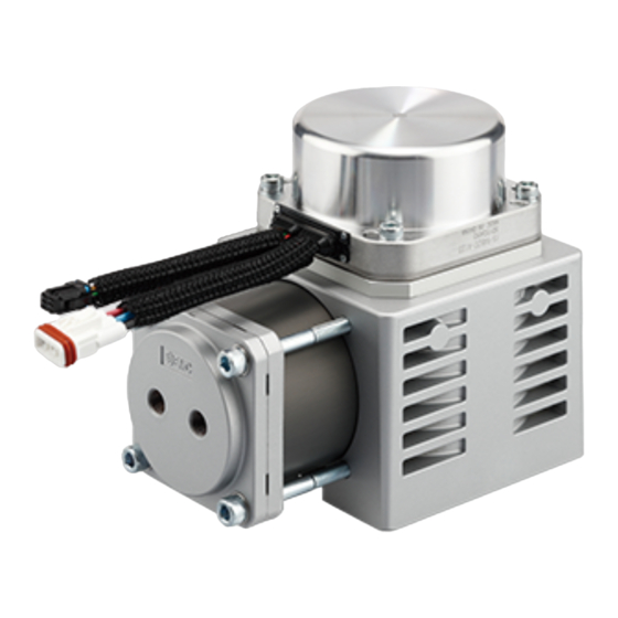
1.3 Compressor construction To MOTOR To SENSOR To POWER Provided by the customer Power supply 24VDC To PRESSURE SWITCH Senser Cable 1m Motor cable 1m DC(+) DC(-) AN05-M5 ISE20A-Y-01-J Silencer Digital pressure switch V124-5LU-M5 Solenoid valve To Inlet port AN10-01 Silencer AKH06-00 Check valve... -
Page 11: Specifications
1.4 Specifications Items Specifications Compression method Reciprocating (oil-free) Max. discharge/ vacuum pressure 0.55MPa/ -70kPa Max. discharge/ vacuum flow rate 10L/min (ANR) Unloader method Digital pressure switch Duty cycle Continuous Compressor AN10-01: 62dB or less Note1 Noise ANB1-01: 55dB or less Operating temperature range 5 to 40 Operating humidity range... -
Page 12: Parts Description
1.5 Parts description The detailed descriptions of each part of the compressor are follows: Name Description Motor power connector Use to connect motor cable. (3 pins) Motor sensor connector Use to connect sensor cable. (6 pins) Function earth Use to connect the earth wire. Caution label Do not remove the caution label under any circumstance. - Page 13 The detailed descriptions of each part of the controller are follows: To controller To compressor Motor cable Sensor cable Label Name Description Use to connect the controller power supply (DC24V). Power supply connector POWER 24V: Connect to the 24 VDC of the power supply (2 pins) GND: Connect to the 0 VDC of the power supply Connect the output of the pressure switch and the power...
-
Page 14: Outline Dimensions
1.6 Outline dimensions The dimensions of the compressor are shown in the diagram below. - 14 -... - Page 15 The dimensions of the controller are shown in the diagram below. 1) Screw mounting 2) DIN rail mounting - 15 -...
-
Page 16: Installation
2. Installation 2.1 How to install the compressor 1) Installing the compressor Air intake and heat exhaust functions use a fan to cool down the compressor. Ensure a clearance of 30mm or more from the installation surface, 30mm or more around the product, and enough space for maintenance. -
Page 17: How To Install The Controller
2.2 How to install the controller 1) How to install The controller can be direct mounted using screws or mounted on a DIN rail. The followings are the descriptions on how to install each type. 1) Screw mounting 2) DIN rail mounting Installation with the DIN rail Installation with four M4 screws Screw direction... - Page 18 3) Mounting location Design the size of the control panel and the installation so that the temperature surrounding the controller is 5 to 40 C or less. Allow 60 mm minimum space between the front of the controller and the door (lid) so that the connectors can be connected and disconnected as shown below. Avoid mounting the controller near a vibration source, such as a large electromagnetic contactor or circuit breaker on the same panel.
-
Page 19: Wiring And Piping
3. Wiring and Piping 3.1 Pressure switch setting This product controls the pressure and performs stop / start (unload / load) by connecting the pressure switch to the controller. Use the designed setting when transmitting the output of the pressure switch to PLC and receiving from the PLC to the controller. - Page 20 2) Operate the pressure switch and configure it to the settings similar to the example below. Refer to the ISE20 series, catalog, and Operation Manual for information on how to configure. Example of positive pressure Load pressure = 0.3MPa, Unload pressure = 0.5MPa: -Output mode: Hysteresis mode -Normal or reversed output: Reversed output -Set pressure value (Threshold value): n_1, n_2=0.3 (Load pressure)
-
Page 21: Wiring
3.2 Wiring The diagrams below show the connections of the compressor and the controller. 1) Connect the compressor. Motor cable Sensor cable 2) Connect the controller. 3) Connect the pressure switch. A wiring example with a solenoid valve is shown below. -... -
Page 22: Piping
3.3 Piping Attempting to start the product with any pressure inside may cause the start-up to be unstable or disabled. To avoid this, prepare the pneumatic circuit to allow the exhaust of any residual pressure into the atmosphere before restarting the product. The diagrams below provide an example pneumatic circuit to be used in conjunction with the wiring diagram from 3.2. -
Page 23: Construction And Parts
4. Construction and parts Cross recessed Stainless steel Brushless DC binding head screw motor Cross recessed Stainless steel Braided tube Resin binding head screw Axial fan Aluminum alloy Cross recessed countersunk head Stainless steel Hexagon socket chromium screw set screw molybdenum steel Plain washer Stee wire... -
Page 24: Alarm Details And Troubleshooting
5. Alarm details The alarm LED will turn on or start to flash when an alarm shown below is generated with the controller. If the cause of the alarm is solved when turning on the power supply again, the alarm LED will turn off and the product will be operable. - Page 25 Revision history 4-14-1, Sotokanda, Chiyoda-ku, Tokyo 101-0021 JAPAN Tel: + 81 3 5207 8249 Fax: +81 3 5298 5362 https://www.smcworld.com Note: Specifications are subject to change without prior notice and any obligation on the part of the manufacturer. © 2023 SMC Corporation All Rights Reserved...
Need help?
Do you have a question about the CRP10 Series and is the answer not in the manual?
Questions and answers