
Summary of Contents for ARC DDU V5.0
- Page 1 DRIVER DISPLAY UNIT ARC/DDU/V5.0 USER MANUAL JULY 2020 RELEASE 1.0 Advanced Rail Controls Private Limited Bangalore-560092...
-
Page 2: Table Of Contents
INDEX INDEX NO. CONTENTS PAGE NO. INTRODUCTION MECHANICAL DESIGN DETAILS OF DDU INTERFACE DETAILS OF DDU OPERATOR CONTROLS OF DDU INDIVIDUAL KEYPAD DETAILS: PXY KEY PAD INDIVIDUAL KEYPAD DETAILS: DPWCS/DDU FUNCTIONAL KEY PAD SCREENS CONTACT DETAILS... -
Page 3: Introduction
IMPORTANT NOTICE This is a sophisticated microprocessor based equipment and can be serviced only by trained skilled personnel. Opening the equipment by any unauthorized person will make the warranty null and void. 1. INTRODUCTION This document describes the technical details of Graphic Driver Display Unit (DDU) used in 3- Phase Electric Locomotives of WAP5, WAP7, WAG9 &... -
Page 4: Mechanical Design Details Of Ddu
2. MECHANICAL DESIGN DETAILS OF DDU DDU USER MANUAL V5.0 - 2 -... -
Page 5: Interface Details Of Ddu
3. INTERFACE DETAILS OF DDU Sl. No Interface Details Connector Type POWER 3 pin sub D 15 pin shell size 3 pin circular MIL-26482 I standard panel mount Male connector (This will be mounted as per the POWER customer requirement, by default this slot will be blanked) 10 pin circular MIL-26482 I standard panel mount Male connector (This will be mounted as... -
Page 6: Operator Controls Of Ddu
OPERATOR CONTROLS OF DDU DDU FUNCTIONAL KEYPAD PXY KEYPAD The DDU has a rugged membrane keyboard on the right-hand side of the display. There are two sections in the key board, are known as “PXY” keypad and “DDU Functional” keypad on the right-hand side. -
Page 7: Screens
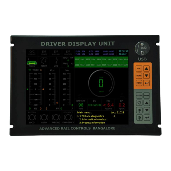
SCREENS The Driver display has pre-defined dedicated screens in order to monitor real time process variables pertaining to a particular section or sub-system of the locomotive. However, such screens are meant for online monitoring by technical staff whenever required. The locomotive driver, however, needs to view the default screen only most of the times. - Page 8 The design philosophy followed is such that all the critical process variables and PIXY screen which are needed to be monitored always by the driver has been provided in a permanent screen area and it will always be available irrespective of any pre-defined screen selected. In any screen, the changing portion is a small area in the space of the speedometer dial of the default screen.
- Page 9 The first graphic mimic in the second row shows the loco type and loco number at bottom, the active cab and the direction selected. The active cab is indicated by a small green dot and the arrow indicates the direction selected. The second graphic mimic displays the status of pantograph.
- Page 10 The battery voltage, when normal, will be shown in green. When the value goes below 86V, it will be shown in red. The brake cylinder pressure (BC) is shown in Boolean form as 'applied' or 'released' depending upon the brake cylinder pressure. Similarly, MR pressure is also shown in Boolean form.
- Page 11 5.2 LIST OF SCREENS In the above condition, if <HOME> button is pressed, default screen will appear. When the list of screen is displayed, one can navigate to a particular screen by pressing <UP> or <DOWN> arrow keys of the upper group of key pads. After selecting the particular screen, when <ENTER> is pressed, the contents of the selected screen will get displayed.
- Page 12 SCREEN 1 : SUB-SYSTEM STATUS In the sub-system status menu, the names of the sub-systems are listed. To navigate to default screen, press <HOME>. To navigate to list of screens, press <ESC>. The isolated sub-system will be shown in red. SCREEN 2 : HIGH VOLTAGE CIRCUIT In the HIGH VOLTAGE CIRCUIT screen, Harmonic Filter status and Hotel Load status is additionally provided.
- Page 13 SCREEN 3: TRACTION CONVERTER In TRACTION CONVERTER screen, converter related parameters are displayed. The screen is split into two columns, one for each traction converter. The process variables displayed include pre-charge & input contactor status, oil pressure & temperatures, input power & ventilation level.
- Page 14 DDU USER MANUAL V5.0 - 12 -...
- Page 15 SCREEN 4: AUXILIARY CONVERTER The Auxiliary Converter screen provides very vital process variable display about the BUR, which will help in easy trouble shooting. The variables include Auxiliary winding voltage, Total current in the auxiliary winding, dc link voltage & dc link current of each BUR, output voltage and output frequency.
- Page 16 SCREEN 6 : AUXILIARY SYSTEM The auxiliary system screen essentially displays the status of various auxiliary machines, as to whether these are OFF or ON. It also indicates the BUR status and BUR input volatge. The auxiliary machines considered are Compressors (1,2), Oil Cooling Blowers (1,2), Oil Pump Converter (1,2), Oil Pump Transformer (1,2), Traction Motor Blower (1,2) &...
- Page 17 DDU USER MANUAL V5.0 - 15 -...
- Page 18 SCREEN 7 : BRAKING SYSTEM The braking system screen displays the process variables related to braking, which include locomotive speed, master controller position (traction/braking region), BE demand and BE Actual, Pneumatic Brake0 Effort demand (when regeneration fails), regenerated power & energy as well as status of compressor.(refer the picture on next page) DDU USER MANUAL V5.0 - 16 -...
- Page 19 SCREEN 8 : ENERY MONITORING The screen for energy monitoring displays the energy consumed and regenerated. The cumulative value is the one taken from the NVRAM of DIA computer, which is available on MVB. The trip energy is calculated by the driver display itself from the time of switching ON. This value is not saved in any memory and will vanish once the locomotive is OFF.
- Page 20 SCREEN 9: TEMPERATURES The temperature screen provides various temperatures recorded by sensors and the same can be compared with the converter input power. The temperatures of transformer oil, traction converter oil and traction motors are displayed along with converter input power for each bogie.
- Page 21 SCREEN 10: PRESSURES This screen shows the pressure variables. It includes Transformer oil pressure, converter oil pressure, MR pressure, BP pressure and status of BC1 & Bc2. (Refer the picture on next page) DDU USER MANUAL V5.0 - 19 -...
- Page 22 SCREEN 11: DIAGNOSIS DDU USER MANUAL V5.0 - 20 -...
- Page 23 SCREEN 12: LANGUAGE SCREEN 13: DRIVER DETAILS This screen is not made active and is reserved for future implementations. The full-fledged implementation would be available in future through an authentication device like a USB stick. The data has to be entered by the driver before the start of the journey. It is not mandatory to enter the data for the functioning of the equipment.
- Page 24 SCREEN 14.1: ANALOG SIGNALS SCREEN 14.1.1: ANALOG SIGNALS -FLG1 FLG1 INPUT SIGNALS SIGNAL SIGNAL NAME IN CHANNEL/SLOT:CONNECT DESCRIPTION FUPLA OR:PIN Angle Transmitter 0101-XAngTrans 12/EA05 Pressure Auto Brake 0101-XPrAutoBkLn 6/EC01 FLG1 OUTPUT SIGNALS TE/BE Meter Bogie-1 0201-XMeterT/B1 2/EG01 TE/BE Meter Bogie-2 0201-XMeterT/B2 4/EI01 /B1 2/EG01...
- Page 25 SCREEN 14.1.4: ANALOG SIGNALS -SLG2 SLG2 ANALOG SIGNALS SIGNAL DESCRIPTION SIGNAL NAME CHANNEL/SLOT: CONNECTOR:PIN Primary Current 0104-XAIpr 1/AA06 Total BUR Current 0104-XAIBUR 2/AC/06 Filter Current 0104-XAIFilt 3/AE06 Pressure TFP Oil 0106-XADruckTR 8/AI06 Pressure SR Oil 0106-XADruckSR 12/DK07 Temperature 1 TFP Oil 0106-XATmp1OelTR 11/DI05:09 Temperature 2 TFP Oil...
- Page 26 MMCBBloMR1 MCB Scavenge Blower to MR1 0102- 4/QA10 MMCBMScBlo1 MCB Oil Pump SR1 0102- 5/QA03 MMCBPumpC1 MCB TFP Pump 1 0102- 6/QA11 MMCBPumpT1 MCB TM Blower 1 0102- 7/QA04 MMCBBloTM1 MCB Scavenge to TM Blower 0102- 8/QA12 MMCBTScBlo1 Earth Fault in 400/110V AC 0102- 9/QD01 Circuit...
- Page 27 SCREEN 14.2.2: DIGITAL SIGNALS HBB2 SCREEN 14.2.2.1: DIGITAL SIGNALS HBB2 INPUT GROUP 1 HBB2 DIGITAL INPUT GROUP 1 SIGNAL DESCRIPTION SIGNAL CHANNEL/SL NAME IN FUPLA CONNECTOR: MCB Compressor 2 0101- 1/OA01 MMCBCompr2 Emergency Stop 0101-LEmgStop 3/OA02 MR Blower OK 0101- 4/OA10 MMRBlowerOk Max TE Limit Switch...
- Page 28 SCREEN 14.2.2.3 DIGITAL SIGNALS HBB2 OUTPUT GROUP 1 HBB2 DIGITAL OUTPUT GROUP 1 SIGNAL DESCRIPTION SIGNAL NAME CONNECTOR Fault Indication Lamp 0201-MLampFInd 1/OG19 Fault Status Lamp 0201-MLampFault 2/OG20 EP Valve Auto Brake Out 0201-BEPAutBkOut 4/OG07 Reset Vigilance Penalty Brake 0201-BResVigPeBk 7/OJ13 Buzzer Black 0201-BBuzzBlack...
- Page 29 SCREEN 14.2.3.2 DIGITAL SIGNALS STB1 INPUT GROUP 2 STB1 DIGITAL INPUT GROUP 2 SIGNAL NAME CHANNEL/SLOT: SIGNAL DESCRIPTION CONNECTOR:PIN FUPLA Temp Relay Control 0102- 1/LA01 Electronics MReTempCEL Cutout Switch Bogie-1 0102- 2/LA09 LSwBogOut1 Cutout Switch Bogie-2 0102- 3/LA02 LSwBogOut2 Switch Configuration 0102-LSwConfig 4/LA10 Switch Fail Mode...
- Page 30 Lamp Configuration 0202- 8/LG03 MLampConfig Lamp Test 0202-BLampTest 9/LG17 VCB On Command (MTDJ) 0202-BVCBOn 10/LG23 VCB On Pulse (EFDJ) 0202- 11/LG24 BVCBOnPulse Contactor Compressor 1 0202- 14/LJ02 BContCompr1 VCB Disable 0202- 15/LG09 BVCBDisable Contactor Self Hold 0202-BContSelfH 16/LG14 SCREEN 14.2.4 DIGITAL SIGNALS STB2 SCREEN 14.2.4.1 DIGITAL SIGNALS STB2 INPUT GROUP 1 STB2 DIGITAL INPUT GROUP 1 SIGNAL NAME...
- Page 31 MCB Scavenge TM Blower 0102- 7/LA04 MMCBTScBlo2 Earth Fault BUR 0102-MEFRBUR 8/LA12 Wish Pan Up 0102-LPanUp 9/LD01 Pressure Switch BC1 0102- 10/LD09 MPrSwBkCyl1 Smoke Warning 0102-MSmogWarn 11/LD02 Fire Equipment Failed 0102-MFailFireEq 12/LD10 Pressure Switch Emergency 0102- 13/LD03 Brake MPrSwEmgBk Pressure Switch Park Brake 0102- 14/LD11 MPrSwParkBk...
- Page 32 SCREEN 14.2.5 DIGITAL SIGNALS SLG1 SCREEN 14.2.5.1 DIGITAL SIGNALS SLG1 INPUT SLG1 DIGITAL INPUTS SIGNAL DESCRIPTION SIGNAL NAME IN CHANNEL/SLOT: CONNECTOR:PIN FUPLA Input Contactor 0103-MLdSEin 9/WD01 Filter Discharge Contactor 0103-MFiltDhcOn 10/WD0 Filter Contactor 0103-MFiltOn 11/WD0 Filter Adaptation Contactor 0103-MFiltAdpOn 12/WD1 Protective Shutdown Wire 0103-MHS-HalteKr 13/WD0...
- Page 33 Filter Contactor 0103-MFiltOn 11/WD02 Filter Adaptation Contactor 0103-MFiltAdpOn 12/WD10 Protective Shutdown Wire 0103-MHS-HalteKr 13/WD03 DC Link Capacitor Pressure 0102-MDruCZK 14/WD11 Pre-Charging Contactor 0103-MSRSEin 15/WD04 External Protective Turn Off 0103-MExtRLgez 16/WD13 Wire SCREEN 14.2.6.2 DIGITAL SIGNALS SLG2 OUTPUT SLG2 DIGITAL OUTPUTS SIGNAL DESCRIPTION SIGNAL NAME CHANNEL/SLOT:...
-
Page 34: Contact Details
G-Block, Sahakaranagar, Bangalore-560 092 Phone: +91 80 42401212, +91 80 42401226 Fax: +91 80 42401213 Cell: + 91 9743715600 E-Mail: <mail@arc.net.in>, <mariappa@arc.net.in> URL : <www.arc.net.in> Lallaguda / Vishakhapatnam / Kazipet / Vijayawada Chaitanya [Base Station: Lallaguda] Cell: + 91 9177368723... - Page 35 Subhash [Base Station: New Delhi] Cell: + 91 9212846380 Tatanagar / Bandamunda Vivek Kumar Mukhi [Base Station: Tatanagar] Cell: + 91 7762905971 Gomoh Ravikumar Vishwakarma [Base Station: Gomoh] Cell: + 91 7050029319 DDU USER MANUAL V5.0 - 33 -...
Need help?
Do you have a question about the DDU V5.0 and is the answer not in the manual?
Questions and answers