Table of Contents
Advertisement
Quick Links
Advertisement
Table of Contents

Subscribe to Our Youtube Channel
Summary of Contents for HP Enterprise Aruba7200 Series
- Page 1 Aruba 7200 Series Controller...
- Page 2 Copyright © Copyright 2019 Hewlett Packard Enterprise Development LP. Open Source Code This product includes code licensed under the GNU General Public License, the GNU Lesser General Public License, and/or certain other open source licenses. A complete machine-readable copy of the source code corresponding to such code is available upon request.
-
Page 3: Table Of Contents
Contents Preface ........................... 5 Guide Overview .....................5 Related Documentation ..................5 Contacting Support ....................6 Chapter 1 7200 Controller..................7 Models ........................7 Package Checklist ....................7 Front Panel ......................8 Dual-Media Ports ....................9 10/100/1000BASE-T (RJ-45) Ports............9 1000BASE-X (SFP) Ports................10 Dual-Media Port LEDs ................10 10GBASE-X (SFP+) Ports ................11 10GBASE-X Port LEDs ................11 Power, Status, and Peered LEDs..............12 LCD Panel .....................12... - Page 4 Installing an AC Power Supply (PSU-350-AC) ..........29 Removing an AC Power Supply..............30 Installing a DC Power Supply (PSU-350-DC) ..........30 Connecting DC Power to the Device ............30 Removing a DC Power Supply..............31 Installing an SFP....................31 Removing an SFP ..................32 Connecting an LC Fiber Optic Cable ............32 Chapter 3 Specifications, Safety, and Compliance..........
-
Page 5: Preface
Preface This document describes the hardware features of the Aruba 7200 Series Controller. It provides a detailed overview of the physical and performance characteristics of each controller model and explains how to install the controller and its accessories. Guide Overview Chapter 1, “7200 Controller”... - Page 6 | Preface | Installation Guide Aruba 7200 Series Controller...
-
Page 7: 7200 Controller
Chapter 1 7200 Controller The Aruba 7200 Series of controllers consists of three enterprise-class, wireless LAN controllers. These controllers connect, control, and intelligently integrate wireless Access Points (APs) and Air Monitors (AMs) into a wired LAN system. Models The 7200 series includes three models that provide varying levels of functionality. Table 4 Aruba 7200 Series Controller Models Number of APs Minimum Supported... -
Page 8: Front Panel
Table 5 Package Contents (Continued) Item Quantity Rack Mounting Brackets M6 x 15 mm Rack Mounting Screws M4 x 8mm Rack Mount Bracket Screws M6 x 7 mm Grounding Screws USB Console Cable Power Cable Aruba 7200 Series Installation Guide (Printed) (This document) Quick Start guide (Printed) End User License Agreement (Printed) Aruba Document Pointer (Printed) -
Page 9: Dual-Media Ports
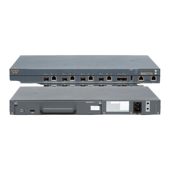
Figure 1 Front Panel of the 7200 Dual-Media Ports The 7200 is equipped with 2 sets of dual-media ports (ports 0 and 1). These ports can utilize either the 1000BASE-X or 10/100/1000BASE-T connections provided. However, the 1000BASE-X fiber connection has priority over the 10/100/1000BASE-T copper connection. If a link is detected on the 1000BASE-X interface, the 10/100/1000BASE-T connection will be disabled. -
Page 10: 1000Base-X (Sfp) Ports
Figure 2 10/100/1000BASE-T Management Port Pin Out Signal Name Function RJ-45 Female Pin-Out BI_DA+ Bi-directional pair +A BI_DA- Bi-directional pair -A BI_DB+ Bi-directional pair +B BI_DC+ Bi-directional pair +C BI_DC- Bi-directional pair -C BI_DB- Bi-directional pair -B BI_DD+ Bi-directional pair +D BI_DD- Bi-directional pair -D 1000BASE-X (SFP) Ports... -
Page 11: 10Gbase-X (Sfp+) Ports
Table 7 1000BASE-X Port LEDs Function LCD Mode Indicator Status LINK/ACT Link status Green (Solid) Link has been established Green (Blinking) Port is transmitting or receiving data No link STATUS Port status Administrative Green (Solid) Port Enabled Port Administratively Disabled Duplex Green (Solid) Full-duplex... -
Page 12: Power, Status, And Peered Leds
Table 8 10GBASE-X Port LEDs (Continued) Function LCD Mode Indicator Status Status Port status Administrative Green (Solid) Port Enabled Port Administratively Disabled Duplex Green (Solid) Full-duplex Speed Green (Solid) 10 Gbps 1 Gbps Power, Status, and Peered LEDs In addition to the LEDs on each individual port, there are three additional LEDs on the front panel that provide overall status of the device. - Page 13 Figure 3 LCD Panel M E N U E N T E P O W S T A T P E E R O L E C O N S Table 10 LCD Panel Components Callout Component Description LCD Screen Used to configure LED behavior and other basic operations Menu Button Used to select the LCD screen menu...
- Page 14 The LED mode menu allows you to choose what information is communicated by the LEDs on each port. Refer to Table 8 on page 11 for descriptions of the LED behavior of each mode. Table 12 LCD Panel Mode: LED Menu Function/Menu Displays Options...
-
Page 15: Disabling The Lcd Screen
Table 14 LCD Panel Mode: Maintenance Function/Menu Displays Options System Reboot Allows you to reboot the controller. Reboot [no | yes] System Halt Allows you to halt the controller. Halt [no | yes] Exit Maintenance Menu EXIT MAINTENANCE Disabling the LCD Screen By default, the LCD screen is enabled. -
Page 16: Console Port
5. Select the file appropriate to your application. The corresponding operating system is in the file name. Console Port A serial console port is provided for connection to a terminal, allowing for direct local management. The port’s RJ-45 female connector accepts an RS-232 serial cable with a male connector. Figure 4 Serial Console Port Pin-Out Serial RJ-45 Female... -
Page 17: Expansion Slot
Expansion Slot The expansion slot is reserved for future use. Rear Panel The rear panel of the Aruba 7200 controller consists of the following components: Two power supply slots One fan tray slot Grounding point Figure 6 Rear Panel Fan Tray The 7200 is equipped with a field-replaceable, hot-swappable fan tray. -
Page 18: Hot Swapping
Hot Swapping Hot swapping allows you to replace a failed fan tray, making it unnecessary to shut down the 7200 during the replacement procedure. Figure 7 Fan Tray Table 16 Fan Tray Components Callout Component Description Left Latch Used to secure the left side of the fan tray to the chassis. Right Latch Used to secure the right side of the fan tray to the chassis. -
Page 19: Power Supply
Power Supply Never insert or remove a power supply while the power cord is connected. Verify that cord has been disconnected from the power supply before installation or removal. The Aruba 7200-series Power Supply adapts electrical power for use with the 7200. The chassis has two slots that can hold individual power supplies to support load sharing, redundancy, and fault tolerance. -
Page 20: Ac Power Supply Overview
AC Power Supply Overview Figure 9 AC Power Supply Table 17 AC Power Supply Components Callout Component Description Latch Used to secure the power supply to the chassis. AC LED AC status LED. DC LED DC status LED. TEMP LED Power supply temperature LED. -
Page 21: Dc Power Supply Overview
Table 18 AC Power Supply Module LEDs (Continued) Description Indicator Status TEMP Power Supply Temperature Green (Solid) Operating Normally Red (Solid) Temperature Alarm in PSU DC Power Supply Overview Figure 10 DC Power Supply T E M P + V E O U T - V E G N D... - Page 22 Table 20 DC Power Supply Module LEDs (Continued) Description Indicator Status DC OUT DC Output Status Green (Solid) Operating Normally Red (Solid) Power Supply Failure TEMP Power Supply Temperature Green (Solid) Operating Normally Red (Solid) Temperature Alarm in PSU | 7200 Controller | Installation Guide Aruba 7200 Series Controller...
-
Page 23: Installation
Chapter 2 Installation Installation of the device should be performed by a trained installation professional. This chapter describes how to install an Aruba 7200 controller using the many mounting options available. The 7200 ships with an accessory kit that includes the equipment needed to install the controller in standard, two-point 19-inch telco rack. -
Page 24: Selecting A Location
Installation or removal of the chassis or any module must be performed in a static-free environment. The proper use of anti-static body straps and mats is strongly recommended. Modules must be kept in anti-static packaging when not installed in the chassis. ... -
Page 25: Installation Steps
Installation Steps To install an Aruba 7200 controller into a two-point 19-inch (48.26 cm) rack system: 1. Place a rack mount bracket over the mounting holes on one side of the controller (see Figure 11). 2. Secure the bracket to the controller using four M4 x 8mm phillips flat head screws and a suitable screwdriver. -
Page 26: Required Tools And Equipment
Figure 12 Rack Mount Installation 5. Leave a minimum of four inches (10cm) of space on the left and right side of the unit for proper air flow and ventilation. See Figure 8 on page 18 for more information about the 7200’s airflow requirements. -
Page 27: Installing And Removing A Fan Tray
2. Lift the power cord retaining clip so it is not blocking the AC power connector. 3. Insert the coupler end of the AC power cord into the AC power connector on the power supply module. 4. Lower the power cord retaining clip over the AC power cord. The 7200 should now be receiving power. - Page 28 Figure 13 Installing a Fan Tray | Installation | Installation Guide Aruba 7200 Series Controller...
-
Page 29: Installing And Removing A Power Supply
Installing and Removing a Power Supply Never insert or remove a power supply while the power cord is connected. Verify that cord has been disconnected from the power supply before installation or removal. Use standard ESD precautions when installing or removing a power supply module. The power supply modules are hot-swappable. -
Page 30: Removing An Ac Power Supply
Removing an AC Power Supply To remove a power supply from your 7200: 1. Lift the power cord retaining clip from the power cord. 2. Remove the power cable connected to the power supply module. 3. Using a Phillips head screwdriver, loosen the hinged captive screw on the front of the power supply module. -
Page 31: Removing A Dc Power Supply
c. Secure the ring lug of the negative (-) DC power source cable to the -VE terminal on the PSU- 350-DC. d. Tighten each screw on the PSU-350-DC terminals until snug using a Phillips-head screwdriver. Figure 16 Connecting Power Cables T E M P + V E O U T... -
Page 32: Removing An Sfp
Figure 17 Installing an SFP Removing an SFP To remove an SFP module: 1. Open and release the latch on the SFP module. 2. Pull and remove the module from the port. Connecting an LC Fiber Optic Cable To connect an LC fiber optic cable into an SFP module: 1. -
Page 33: Chapter 3 Specifications, Safety, And Compliance
Chapter 3 Specifications, Safety, and Compliance 7200 Specifications Physical Device Dimensions (without mounting brackets) (HxWxD) All Models: 1.75” x 17.5” x 17.5” All Models: 4.4cm x 44.5cm x 44.5cm Device Weight (with one AC power supply installed) ... -
Page 34: Regulatory Models
Regulatory Models This document covers the following models: Table 21 Regulatory Model Numbers Part Number Regulatory Model Number 7210, 7210-IL, 7210-US, 7210DC, 7210DC-US, and 7210DC-IL ARCN0100 7220, 7220-IL, 7220-US, 7220DC, 7220DC-IL, and 7220DC-US ARCN0101 7240, 7240-IL, 7240 -US, 7240DC, 7240DC-IL, 7240DC-US, 7240XM, and ARCN0102 7240XMDC This device complies with Part 15 of the FCC Rules. -
Page 35: Battery Statements
This product complies with 21 CFR Chapter 1, Subchapter J, Part 1040.10, and IEC 60825-1: 1993, A1: 1997, A2: 2001, IEC 60825-2: 2000. For continued compliance with the above laser safety standards, only approved Class 1 modules from our approved vendors should be installed in the product. Although this controller has been tested to up to 1kV per CE immunity requirements, this product requires surge protection to be provided as part of the building installation to protect against unidirectional surges resulting from electrical switching and lightning strikes. -
Page 36: China Rohs
China RoHS Aruba products also comply with China environmental declaration requirements and are labeled with the “EFUP 50” label shown at the left. Hazardous Materials Declaration Hazardous Substances) Chromium VI Polybrominated Polybrominated (Parts) Lead Mercury Cadmium Compounds Biphenyls Diphenyl Ether (Pb) (Hg) (Cd)
Need help?
Do you have a question about the Aruba7200 Series and is the answer not in the manual?
Questions and answers