Table of Contents
Advertisement
Quick Links
Advertisement
Table of Contents

Summary of Contents for Cyndar Electronic Technology HL-1601
- Page 1 CYNDAR Safety Edge Sensor Product manual XD-Safety Contact Edge-202012...
-
Page 2: Table Of Contents
Directents Directents 1. Safety edge Product profile ........................3 2. Safety Touch Technology Selection Table ..................4-6 Regular type ..............................4 Small size ................................ 5 Special type ..............................5 Type selection recommendations ......................6 3. security and edge contact configuration type and technical parameters ......6-8 (1) Wire type .............................. -
Page 3: Safety Edge Product Profile
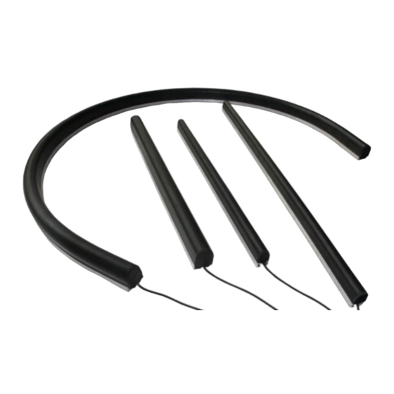
1. Safety edge Product profile Safe contact edges are flexible bending bands or circles. It can be fixed to dangerous edges of moving parts such as tire molding, lift safety doors, machine workbench and electric doors. When the moving components hits the operator or the moving components, these flexible safety edges are compressed and transmitted to the power source has stopped this movement of these components. -
Page 4: Safety Touch Technology Selection Table
2.Safety touch edge technology selection table Regular type... -
Page 5: Small Size
Small size Special type... -
Page 6: Type Selection Recommendations
Type selection recommendations See the following table: The dimensions are reference values Small AGV, garage access Application of various Application of AGV, electric Application of AGV, electric control, industrial electric doors, industrial door and industrial fields door and industrial fields applications and civil fields Application of AGV, electric... -
Page 7: Wiring Configuration
(2) Wiring configuration Determine the wiring configuration according to the number of safety contact edges (sensors) connected in series. (Up to 5 safety contact edges can be connected in series) Configure Number Outline drawing Output Type Wiring configuration 2-wire cable One-end outgoing line 2-line cable (2- Safe touch line system) -
Page 8: Safety Contact Edge Technical Parameters
Blind area Standard Signal hstand temperatur Model Number force value Distance: Radius: Material Scope wiring harness mode voltage current HL-1601 ≤ 30N 3-5mm ≥ 120mm HL-1603 ≤ 30N 3-5mm ≥ 100mm HL-1605 ≤ 30N 3-5mm ≥ 120imn HL-1606 ≤ 30N 3-5mm... -
Page 9: Installation Instructions
4.Installation instructions Safety contacts must be installed by the designated person 1. For facilitate installation of edge installation. The mounting 6.To make the safety edge easier to install, soapy water should be base must be secured to a flat surface. If the safety contact edge sprayed on the mounting base and the safety edge. -
Page 10: Safety Touch Edge Sensor Wiring Simple Description
5.Simple description of safety touch edge sensor wiring Apply vertical pressure to the safety contact edge to make the conductors of the internal induction belt contact each other, which causes the resistance and current to change, which is further analyzed by the control device. If the installation is correct, as long as the internal induction belt is not damaged, the safety edge cover can function normally even if it is damaged. - Page 11 Safety contact edge standard safety controller model: Tner-A31 A1: is connected to + 24V ± 10% (20V~26V) A2: to 0V Automatic reset: Diial switch to A Manual reset: Diial switch to M (No resistance contact edge) Tner-A31 safety relay connection method: Touch edge 1: Red and black lines: connect T1 and R1, Touching edge 2: Red wire and black wire: connect to T2 and R2 in no particular order.
- Page 12 (Touch edge with resistance) Tner A31 safety relay connection method: Touch edge 1: Red and black lines: connect T1 and R1, Touch edge 2:: red line and black line: connect T2 and R2,. If not touch edge 2, connect a 5.6k resistance.
-
Page 13: Safety Relay Tner-A31 Technical Parameters
6.Safety Relay Tner-A31 Technical Parameters Power supply Power supply supply 24V DC Voltage tolerance +10%/-20% Power consumption 2.9W Output Relay safety output 3NO + 1NC Transistor signal output <500mA 24VDC Relay contact capacity AC-1 6A/250VAC/1500VA AC-15 4A/240VAC DC-1 6A/24VDC/150W DC-13 4A/24VDC Maximum switching 12A(assigned on all security output contacts) -
Page 14: Security Notes
Safety characteristics PL Performance Level L EN ISO 13849-1:2015 Category Category EN ISO 13849-1:2015 Cat.4 SIL CL EN 62061:2005 + A2:2015 SIL CL 3 PFH d [1 / h] EN 62061:2005 + A2:2015 2.10E-09 7.Safety contact precautions 1) Storage and use environment requirements Do not save or use this product in a long-term direct sunlight environment.
Need help?
Do you have a question about the HL-1601 and is the answer not in the manual?
Questions and answers