
Summary of Contents for Müller-Elektronik EDS-P
- Page 1 Service manual EDS-P Pneumatical Single Nozzle Switching System Version: V5.20170815 3030308301-02-EN-200 Read and follow these operating instructions. Keep these operating instructions in a safe place for later reference.
- Page 2 Company details Document Service manual Product: Pneumatical Single Nozzle Switching System Document number: 3030308301-02-EN-200 As of software version: 1.5 Original language: German Copyright © Müller-Elektronik GmbH & Co.KG Franz-Kleine-Straße 18 33154 Salzkotten Germany Phone: ++49 (0) 5258 / 9834 - 0 Fax: ++49 (0) 5258 / 9834 - 90 Email: info@mueller-elektronik.de Homepage: http://www.mueller-elektronik.de...
-
Page 3: Table Of Contents
Table of contents Table of contents For your safety Basic safety instructions Target group for this service manual Directional information in these instructions Product description Basic principles of the EDS single nozzle switching system System overview Information on the rating plate Intended uses Installation Install the EDS communication module... -
Page 4: For Your Safety
For your safety Basic safety instructions For your safety Basic safety instructions Please read the following safety instructions carefully before using the product for the first time. ▪ Before installation, switch off the engine and the tractor's ignition. ▪ Do not make any unauthorized modifications to the product. Unauthorized modifications or use may impair safety and reduce the service life or operability of the unit. -
Page 5: Product Description
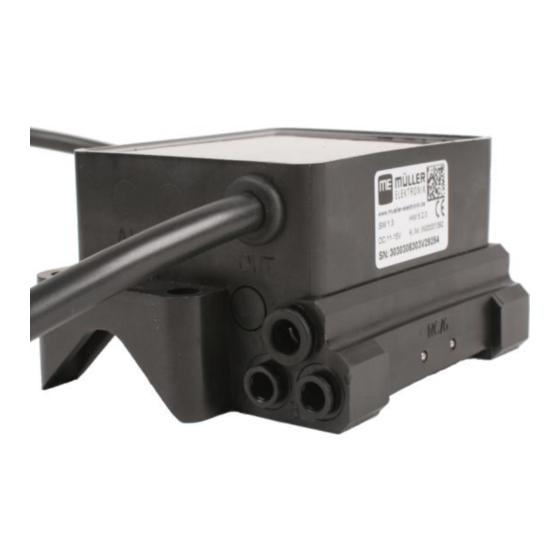
Product description Basic principles of the EDS single nozzle switching system Product description Basic principles of the EDS single nozzle switching system The single nozzle switching system [also called EDS] is a system that serves to directly open and close each nozzle on a field sprayer. This makes it possible to reduce the number of overlaps more effectively than with conventional systems, which can only open and close entire sections. - Page 6 ▪ the type of the multiple nozzle holders that they can control ▪ the item number Pneumatic EDS module (or EDS-P module). The following labels can be found on the module casing Output (OUT) and input (IN) of the EDS Bus...
-
Page 7: Information On The Rating Plate
Product description Information on the rating plate You can see it by the item number on the rating plate [➙ 7]. The various item numbers can be found in Section: Spare parts [➙ 24] Information on the rating plate The rating plate is located on the back of the EDS modules. Abbreviations on the rating plate Abbreviation Meaning... - Page 8 Product description Intended uses Individual nozzle switching with double nozzle holders and two sections Pairwise nozzle switching with single nozzle holders and four sections Section control with single nozzle holder. Section control with double nozzle holder. V5.20170815 3030308301-02-EN-200...
- Page 9 Product description Intended uses Section control with EDS modules. In this version single nozzle holders are installed every 25 cm. 3030308301-02-EN-200 V5.20170815...
-
Page 10: Installation
▪ Only use pneumatic hoses made of hard plastic like polyamide (PA). Soft hoses, e.g. made of polyurethane (PU) or polyethylene (PE), can cause leaks in the connection area of the EDS module. ▪ Do not paint the EDS modules. Installation example: EDS-P module installed directly over a quadruple nozzle holder V5.20170815 3030308301-02-EN-200... -
Page 11: Connecting The Nozzle Holders To The Eds Modules
Installation Connecting the nozzle holders to the EDS modules Universal bracket M5 for attachment to the pipe Cable for the EDS line. The main pneumatic line cannot be seen on this photo. Each pneumatic valve is connected with a hose to one nozzle. The nozzle holder is located directly below the EDS module. -
Page 12: Connecting The Cable
Installation Connecting the cable ▪ The pneumatic system must include a central pressure regulator with filter and a water separator. ▪ Compressed air quality: Technical characteristics of the EDS modules [➙ 22] ▪ Operating pressure: Technical characteristics of the EDS modules [➙ 22] EDS modules and the pneumatic line EDS Module Hose to the air compressor of the field sprayer... -
Page 13: Connecting The Amp Connectors
Installation Connecting the AMP connectors Input EDS module Output EDS module Outer EDS modules There is one EDS module remaining on each side of the boom where the output cannot be connected to another EDS module. The outer outputs must be closed using the supplied terminating plugs. Connecting the AMP connectors Procedure This is how to connect two AMP connectors:... - Page 14 Installation Separating the AMP connectors ⇨ You will hear a loud clicking sound. ⇨ The locking device has been released. 2. Pull out the red locking device of the AMP socket all the way to the end. 3. Pull the connector out of the socket. V5.20170815 3030308301-02-EN-200...
-
Page 15: Configuring The Single Nozzle Switching
Configuring the single nozzle switching Configuring the EDS communication module on the terminal Configuring the single nozzle switching You must configure the individual nozzle switching in the application job computer SPRAYER- Controller 3.0 job computer. Configuring the EDS communication module on the terminal 4.1.1 Open the application of the EDS communication module Procedure... -
Page 16: Allocating The Addresses For The Eds Modules
Configuring the single nozzle switching Configuring the EDS communication module on the terminal Function icon Meaning Indicates the EDS modules on which errors were detected [➙ 20]. Open the diagnostic screen of the EDS modules [➙ 20]. 4.1.3 Allocating the addresses for the EDS modules For the sprayer job computer to be able to properly switch the pneumatic valves, every EDS module must have a clear address. -
Page 17: Configuring The Power Supply Of The Eds Modules
Configuring the single nozzle switching Configuring the EDS communication module on the terminal - Activate the demo function. ⇨ The nozzles will be opened successively from left to right. 4. Check if the nozzles are opened in the correct sequence. If not, it is possible that valves were connected rotated. -
Page 18: Configuring Section-Control For Eds
Configuring the single nozzle switching Configuring SECTION-Control for EDS 3. Set the parameters. - Optionally restore the standard values. - Transmit the settings to the EDS modules. ⇨ The following message appears: “The parameters have been transmitted to the modules.” 6. -
Page 19: Operating The Single Nozzle Switching
Operating the single nozzle switching Operating the single nozzle switching As soon as the EDS system is installed and configured, the work screen of the sprayer job computer application changes. Nothing changes with the operation of the field sprayer. On the following diagram, you can see how the single nozzle switching is shown on the work screen: Representation of the switched EDS modules in the sprayer job computer application Activated SECTION-Control Switched-off nozzles... -
Page 20: Troubleshooting
Troubleshooting Search for faulty EDS modules Troubleshooting The communication module can check the status of the EDS modules and make it easier to diagnose errors. You can perform the following actions to search for errors: ▪ View system detected errors ▪... -
Page 21: After A Modul Change
Troubleshooting After a modul change After a modul change After replacing an EDS module, reallocate the addresses for the EDS modules. [➙ 16] Alarm messages Possible alarm messages Alarm text Possible cause Remedial measure Configuration error! The number of nozzles that 1. -
Page 22: Technical Specifications
Technical specifications Cable harness pin assignment Technical specifications Cable harness pin assignment EDS module cable pin assignment Signal Signal Signal 12 VL Address allocation 0 VL 0 VL 0 VE 12 VL CAN_H EDS-BUS 12 VE 0 VL CAN_L EDS-BUS Communication module pin assignment Signal Signal... - Page 23 Technical specifications Technical characteristics of the EDS modules Compressed air temperature -5°C - +50°C Miscellaneous The pneumatic system must include a central pressure regulator with filter and a water separator. The set pressure must be adjusted to 5 bar. To save power, the EDS modules are operated in PWM mode 20ms after being switched on. 3030308301-02-EN-200 V5.20170815...
-
Page 24: Spare Parts
Spare parts Spare parts Pneumatic EDS Modules Item number Item name Characteristics 3030308303 ME_AR EDS module 4-fold 6mm air single For single nozzle holders 3030308304 ME_AR EDS module 4-fold 6mm air double For double nozzle holders 3030308305 ME_AR EDS module 4-fold 6mm air quadruple For quadruple nozzle holders Communication module Item number... - Page 25 Spare parts Others Item number Item name Comment 3130308300 Universal bracket to attach an EDS module 2 pieces + 4 washers, 4 self-locking nuts M5 3130308311 ME_ST CAN terminator plug 120Ohm, 10-pin. AMP connector 3030308301-02-EN-200 V5.20170815...
Need help?
Do you have a question about the EDS-P and is the answer not in the manual?
Questions and answers