Table of Contents
Advertisement
Advertisement
Table of Contents

Summary of Contents for JUNCTEK KH-F Series
- Page 1 JUNCTEK...
- Page 2 JUNCTEK KH-F series coulometer Shunt Sampling User’s Manual Rev1.0 March 2023 (The pictures in the manual are for reference only)
- Page 3 Copyright Hangzhou Junce Instruments Co., Ltd. all right reserved. Trademark Information JUNCTEK is a registered trademark of Hangzhou Junce Instruments Co., Ltd. Notices JUNCTEK products are covered by P.R.C. patents, issued and pending. This document replaces all previously published documentation.
-
Page 4: Safety Requirement
Do Not Operate With Suspected Failures If you suspect that any damage may occur to the meter, have it inspected by JUNCTEK authorized personnel before further operations. Any maintenance, adjustment or replacement especially to circuits or accessories must be performed by JUNCTEK authorized personnel. -
Page 5: Notices
JUNCTEK Do Not Operate in an Explosive Atmosphere To avoid personal injuries or damage to the meter, never operate the meter in an explosive atmosphere. Keep Meter Surfaces Clean and Dry To avoid dust or moisture from affecting the performance of the meter, keep the surfaces of the meter clean and dry. -
Page 6: Table Of Contents
JUNCTEK Contents Guaranty and Declaration ..............I Safety Requirement ................II General Safety Summary ...................II Notices ......................... III Inspection ....................2 Chapter 1 Overview ................3 1.Brief Introduction ....................3 2.Dimensions ....................... 4 3.Specification ..................... 6 Chapter 2 Meter Introduction ............... 8 1. -
Page 7: Inspection
JUNCTEK Inspection When you get a new KH-F series coulometer, it is recommended that you inspect the meter according to the following steps. Inspect the Packaging If the packaging has been damaged, do not dispose the damaged packaging or cushioning materials until the shipment has been checked for completeness and has passed both electrical and mechanical tests. -
Page 8: Chapter 1 Overview
Chapter 1 Overview 1.Brief Introduction The KH-F series multifunctional voltage and current meter is a new type of coulomb meter that can measure various parameters such as voltage, current, power, charging and discharging capacity, watt-hour, and more. It also has... -
Page 9: Dimensions
JUNCTEK 2.Dimensions Dimension of display module Hole bitmap of display module Note: display module inlay hole size: 85.1 * 58.1mm Dimension of measurement module Hole bitmap of measurement module Dimension of the 100A sampler Hole bitmap of the 100A sampler... - Page 10 JUNCTEK Dimension of the 400A sampler Hole bitmap of the 600A sampler...
-
Page 11: Specification
JUNCTEK 3.Specification Model KH110F KH140F KH160F Sampling method The Shunt The Shunt The Shunt Voltage measurement range 0-120V 0-120V 0-120V (External power supply) Voltage measurement range 10-120V 10-120V 10-120V (Self-powered) Voltage resolution 0.01V 0.01V 0.01V Current measurement range 0~100A 0~400A... - Page 12 JUNCTEK Communication address P01-P99, 99 in total...
-
Page 13: Chapter 2 Meter Introduction
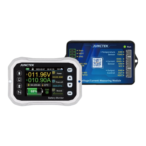
JUNCTEK Chapter 2 Meter Introduction 1. Introduction of display module Figure 2-1-1 KH-F series display module diagram Table 2-1-1 KH-F series display module diagram instructions Description Description LCD screen 【▼】button 【SET】button 【OK】button Communication port 【▲】button (1).LCD screen A 2.4-inch TFT color LCD display screen shows the menu of current functions and settings of parameters, etc. - Page 14 JUNCTEK On the main interface, pressing the 【OK】 button briefly can control the relay on and off if there is one; long-pressing the 【 OK】button can quickly lock or unlock the buttons. (6).Communication port Used to connect with the measurement module.
-
Page 15: Introduction Of The Measurement Module
JUNCTEK 2.Introduction of the measurement module Figure 2-2-1 KH-F series measurement module diagram Table 2-2-1 Instructions diagram of the KH-F series measurement module Description Description 485 communication Indicator light display interface Relay output 2wires&3wires switch control interface Power supply interface... - Page 16 JUNCTEK (5).Display screen communication interface Connected to the display module,when the measurement module is powered, this communication interface is live. From left to right, they are: B, A, GND, +5V. (6).Relay output control interface The relay output control interface can be used with the relay. From left to right, they are: GND, OUT, VEXT.
-
Page 17: Introduction Of The Sampler
JUNCTEK 3.Introduction of the Sampler Figure 2-3-1 KH-F series of the Sampler diagram Table 2-3-1 KH-F series of the Sampler diagram instructions Description Description The Sampler interface (1).Sampler interface Connected to the sampler interface of the measurement module for measuring... -
Page 18: Introduction Of The Display Interface
JUNCTEK 4. Introduction of the display interface Figure 2-4-1 KH-F series display interface diagram Table 2-4-1 KH-F series display interface diagram instructions Description Description Output status Data record Keypad lock status Current direction Actual time External temperature Communication address Battery remaining capacity... - Page 19 JUNCTEK Represents the current actual time. (4). Communication address The communication address range is P01-P99, with P01 representing the current communication address as P01, and the data viewed is for the P01 address. (5). Communication signal indication The current graphic represents that the display module and measurement module are connected normally.
- Page 20 JUNCTEK (12). Remaining capacity Represents the remaining capacity of the battery through charge and discharge, remaining capacity = preset battery capacity -accumulated capacity (13). Measured current value Represents the actual current value measured by the sampler. (14). Measured voltage value Represents the voltage value measured by the voltage measurement interface in the power supply interface.
-
Page 21: Chapter 3 Basic Operation Of The Meter
JUNCTEK Chapter 3 Basic Operation of the Meter 1.System settings System settings instructional video: On the main interface, press the 【SET】button to enter the system settings page, and use the 【▲】and 【▼】buttons to switch between functions. Press the 【OK】button to enter the setting options. - Page 22 JUNCTEK and Celsius, and then press the 【OK】button to confirm the change. 5). Preset battery capacity: 0000.0Ah In the system settings interface, press the【▲】【▼】buttons to switch to the preset battery capacity setting. Press the 【OK】button, and the cursor will select the value. Press the 【▲】 【▼】 buttons to change the value, and press the 【OK】...
- Page 23 JUNCTEK turn off, and the screen will immediately turn on once there is current. 10).Bluetooth pairing password The Bluetooth pairing password is 0000 by default. The Bluetooth pairing password can only be modified through the display screen, and the mobile APP cannot be modified.
- Page 24 JUNCTEK open or normally closed based on the actual relay mode connected. 15).Address matching In the system settings interface, press the 【▲】【▼】keys to switch to the address matching setting. Short press the 【OK】key to select the value with the cursor. Use the 【▲】 【▼】 keys to switch the communication address, and press the 【OK】key again to confirm the communication address between the...
- Page 25 JUNCTEK circuit and activate the protection function. 18).Undervoltage protection: 0.00-120.00V In the system setting interface, press the 【▲】【▼】 buttons to switch to undervoltage protection setting. Press the 【OK】 button to select the value, use the 【▲】 【▼】 buttons to change the value, press the 【OK】 button to switch the digit, and switch from the smallest digit to the highest digit.
- Page 26 JUNCTEK The protection function requires the purchase of an additional relay. If no relay is installed, do not set this value. Install the relay in the circuit to enable the protection function and cut off the circuit when necessary. 21).Over power protection: 0-12000.00W/48000.00W/72000.00W (depending on the machine model) In the system settings interface, press the 【▲】【▼】buttons to switch to the...
- Page 27 JUNCTEK recovery time setting. Press the 【OK】 button briefly to select the value with the cursor. Use the 【▲】【▼】 buttons to change the value, then press the 【OK】 button again to confirm the recovery time setting. When the value is set to 00s, the protection status will last until the 【OK】...
-
Page 28: Wiring Method
JUNCTEK 2.Wiring method Wiring method instructional video: (1). Self-powered wiring method If the voltage range of the battery being tested is between 10-120V during normal operation, the self-powered wiring method can be used. First, switch the power selection interface to "2W". Then, when wiring, connect the positive pole of the battery to the "Vsns"... - Page 29 JUNCTEK with the "LOAD-" symbol. It is best to use a copper nose for the connection to ensure stability. During charging, the direction of the current symbol is green and shows charging, and the remaining capacity value increases. During discharging, the direction of the current symbol is sky blue and shows discharging, and the remaining capacity value decreases.
- Page 30 JUNCTEK Figure 3-2-3 External Power Relay Wiring Method (Wiring method for KH140F as a example)
-
Page 31: Communication Protocol Control
JUNCTEK 3.Communication Protocol Control We only provide communication protocol, and users can perform secondary development based on the communication protocol. (1). Overview The control instructions are generally in the form of command lines, and the communication rate is 115200. Commands are sent from the PC, parsed and executed by the local machine, and the results are returned to the PC. - Page 32 JUNCTEK Turn off output status and data recording. Date Setting :W11=1,0,23,2,7, Set the date to February 7, 2023. Time Setting :W12=1,0,10,15,0, Set the time to 10:15:00. Temperature Unit :W13=1,0,1, Last digit 1: ℉, 0: ℃ Setting Data Recording :W14=1,0,1, Last digit 0: on, 1: off...
- Page 33 JUNCTEK fine-tuning. (The value only represents fine-tuning factor. The larger the absolute value of the value, the greater the amplitude of the fine-tuning.) Set current calibration to increase current fine-tuning. Set current calibration to -20, decrease current fine-tuning. Current Calibration :W30=1,121,120, (...
- Page 34 JUNCTEK (3). R command The R command is a read command, and its command format is basically the same as the write command format, which is not repeated here. The following are example data returned by the machine. send Read...
- Page 35 JUNCTEK February 8th, 2023; 12418 represents time 11:24:18. represents communication address; 69 represents checksum; 2000 represents overvoltage protection set to 20.00V; 1000 represents undervoltage protection set to 10.00V; 2000 represents over-discharge current protection set to 20.00A; 3000 represents over-charge current protection set to 30.00A;...
- Page 36 JUNCTEK represents temperature protection set to -20℃; 0 represents current temperature unit Celsius; represents Fahrenheit) 4321 represents Bluetooth password set to 4321; 2 represents data logging with data interval of 3 seconds per record;...
-
Page 37: Mobile Control
JUNCTEK 4.Mobile Control (1). Android APP user manual Installation and operation video of the Android APP: 1). APP Download Server download link: http://68.168.132.244/KH/KH-F.apk If you don't know how to download or can't download it, you can ask customer service personnel for the software. - Page 38 JUNCTEK Figure 3-4-4 Main Figure 3-4-6 System Figure 3-4-5 line curve interface Settings - Basic settings Figure 3-4-7 System Figure 3-4-8 System Settings - Protection Settings - Advanced Figure 3-4-9 About us settings settings 5). APP operation instructions Connection...
- Page 39 JUNCTEK Open the APP on the homepage and click the search icon in the upper right corner to search for the corresponding Bluetooth device. After selecting the corresponding Bluetooth device, the interface will display "Connected," and the search icon in the upper right corner will change to "Disconnect," with the machine model displayed, indicating that the connection has been completed.
- Page 40 JUNCTEK Data clearing: Click on the data clearing button, and the 'Clear accumulated data' dialog box will appear, allowing for setting of the data recording time interval, and clearing of historical data when confirmed, as shown in Figure 3-4-19. Percentage of remaining capacity : Click on the battery icon, and the...
- Page 41 JUNCTEK Output status off Overvoltage protection Voltage calibration Figure 3-4-16 Figure 3-4-17 Figure 3-4-18 Current calibration Voltage range Max. current value Figure 3-4-20 Figure 3-4-19 Figure 3-4-21 Percentage of remaining Data clearing Preset battery capacity capacity...
- Page 42 JUNCTEK Figure 3-4-22 Figure 3-4-23 Figure 3-4-24 Temperature calibration Temperature unit Data record Line curve interface operation Real-time voltage and current curve: When the blue arrow icon appears before the text of real-time voltage and current curve, it means that the voltage and current curve is selected.
- Page 43 JUNCTEK the historical voltage and current curve. Click it and select the time range for exporting the curve. After confirming the selection, the export progress will be displayed on the screen. When the progress bar is full, it means the curve data export is successful.
- Page 44 JUNCTEK Figure 3-4-30 Figure 3-4-28 Figure 3-4-29 Customized export Export curve Select time range curve Figure 3-4-31 Figure 3-4-32 Select time range View curve System Settings Interface - Basic Settings Temperature Unit: Click the temperature unit button, the 'Temperature unit'...
- Page 45 JUNCTEK dialog box will pop up, and you can choose Celsius or Fahrenheit. As shown in Figure 3-4-33. Preset effective capacity: Click the preset effective capacity button, the 'Preset battery AH.' dialog box will pop up, enter the corresponding value and click OK to complete the modification, as shown in Figure 3-4-34.
- Page 46 JUNCTEK Figure 3-4-36 Data record System Settings Interface - Protection Function Settings OVP overvoltage protection: Click the OVP overvoltage protection button, and the "Overvoltage protection" dialog box will pop up. Enter the corresponding value and click OK to complete the modification, as shown in Figure 3-4-37 below.
- Page 47 JUNCTEK OTP Over temperature protection: Click the OTP over temperature protection button, and the "Over temperature protection" dialog box will pop up. Enter the corresponding value and click OK to complete the modification. Entering "--℃" means to turn off the over temperature protection, as shown in Figure 3-4-42 below.
- Page 48 JUNCTEK Figure 3-4-39 OCP Figure 3-4-37 OVP Figure 3-4-38 LVP discharge overcurrent overvoltage protection undervoltage protection protection Figure 3-4-40 NCP Figure 3-4-41 OPP Figure 3-4-42 OTP over charging overcurrent overpower protection temperature protection protection...
- Page 49 JUNCTEK Figure 3-4-43 LTP low Figure 3-4-44 Figure 3-4-45 Protection temperature protection Low capacity reminder recovery time Figure 3-4-46 Protection Figure 3-4-47 delay time Relay mode System settings interface - Advanced Settings Full voltage: Click on the full voltage button, a dialog box labeled "Full...
- Page 50 JUNCTEK complete the modification, as shown in Figure 3-4-48. Full current: Click on the full current button, a dialog box labeled "Full current" (0-20%)will appear. Enter the corresponding value and click OK to complete the modification, as shown in Figure 3-4-49.
- Page 51 JUNCTEK upgrade process. After the upgrade is completed, 'Upgrade successful' will be displayed. The firmware upgrade order is shown in Figure 3-4-56 Firmware Upgrade 01, Figure 3-4-57 Firmware Upgrade 02, Figure 3-4-58 Firmware Upgrade 03, Figure 3-4-59 Firmware Upgrade 04, and Figure 3-4-60 Firmware Upgrade 05.
- Page 52 JUNCTEK Figure 3-4-51 Figure 3-4-52 Figure 3-4-53 Detection time Set address Zero current memory Figure 3-4-54 Figure 3-4-55 Restore Figure 3-4-56 Restart the instrument factory settings Firmware upgrade 01 Figure 3-4-57 Figure 3-4-58 Figure 3-4-59 Firmware upgrade 02 Firmware upgrade 03...
- Page 53 JUNCTEK Figure 3-4-60 Firmware upgrade 05 Mobile APP theme Theme: Click the theme button to pop up the "Theme" pop-up box, you can choose blue or yellow. As shown in Figure 3-4-61 Main Interface, Figure 3-4-62 Line curve, Figure 3-4-63 System Settings - Basic Settings, Figure 3-4-64 System Settings - Protection Function settings, Figure 3-4-65 System Settings - Advanced settings, Figure 3-4-66 About us.
- Page 54 JUNCTEK Figure 3-4-61 Figure 3-4-62 Figure 3-4-63 System Main interface Line curve Settings - Basic settings Figure 3-4-64 System Figure 3-4-65 System Settings - Protection Settings - Advanced Figure 3-4-66 About us function settings settings About Us Interface Operations...
- Page 55 (2). Instructions for using the IOS app 1). Downloading the app Search for "KH-F Series" in the Apple Store to download or copy the link to your browser: https://apps.apple.com/cn/app/kh-f/id1665076881 2). Mobile App Software Installation The software only supports IOS 9.0 or above. The first time the software links to Bluetooth, it will access Bluetooth, please agree to access.
- Page 56 JUNCTEK Figure 3-4-69 Main Figure 3-4-71 System Figure 3-4-70 Line curve interface Settings - Basic settings Figure 3-4-72 Figure 3-4-73 Figure 3-4-74 System Settings - System Settings - About us Protection settings Advanced settings 5). App operation instructions The operation for Apple devices is the same as that for Android devices...
-
Page 57: Chapter 4 Troubleshooting
Chapter 4 Troubleshooting The following are possible malfunctions and troubleshooting methods that may occur during the use of the KH-F series. If you encounter any of these malfunctions, please follow the corresponding steps to troubleshoot. If you cannot resolve the issue, please contact JUNCTEK and provide your device information. -
Page 58: Chapter 5 More Product Information
The 'KH-F Series Communication Protocol' provides the communication protocol for KH-F series products. The 'KH-F Series English User Manual' provides an introduction to the functions and operation methods of this product, as well as the possible faults that may occur during use and their corresponding solutions. -
Page 59: Chapter 6 Contact Us
JUNCTEK Chapter 6 Contact Us If you have any questions or needs regarding the use of this product or this manual, please contact JUNCTEK. Email: junce@junteks.com Website: www.junteks.com... -
Page 60: Appendix 1: Interface English And Abbreviations
JUNCTEK Appendix 1: Interface English and Abbreviations English English abbreviation Data Record Record Language Selection Language Sound Options Sound Preset Battery Capacity AH.Preset Percentage Of Remaining Capacity AH.Remaining Bluetooth Password BTE Password Over Voltage Protection Low Voltage Protection Charge Current Protection...
Need help?
Do you have a question about the KH-F Series and is the answer not in the manual?
Questions and answers