
Summary of Contents for DSI Buxco FinePointe
- Page 1 DSI Buxco® FinePointe™ Pulmonary Function Test USER MANUAL Publication 014181-001 Rev 02...
-
Page 2: Table Of Contents
Table of Contents Essential Safety Notes ..............................5 Environmental Conditions ............................5 Hazards and Warnings ............................... 5 Welcome ..................................7 What you will be learning ............................7 Application Overview ..............................8 Pulmonary Function Testing (PFT) ..........................8 How It Works ................................9 PFT Test ................................... - Page 3 Measuring Dead Space in the Manifold ........................34 Boyle’s Law Method ............................34 Alternate Boyle’s Law Method Without P ....................... 35 Pressure Conversions and Useful Information ....................36 Hardware Configuration in FinePointe Control Panel ..................... 37 System Calibration ............................... 42 Definitions of Signals ...............................
- Page 4 FVC Value is Wildly Different Than IC ......................... 85 Appendix D - Suggested Reading ..........................86 Contact Information ..............................87 DSI Technical Support—North America ......................87 DSI Technical Support—Europe .......................... 87 Page 4 Pulmonary Function Test • Publication 014181-001 Rev 02 • www.datasci.com...
-
Page 5: Essential Safety Notes
Only use a detachable power cord (AC/DC adapter) that allows for protective earthing and is a minimum of 18 AWG. This cord will need to have appropriate agency approvals, such as UL, CSA. DSI cannot guarantee the safety of this device if used other than intended or used by any procedures other than those described in this manual. - Page 6 Orient the Equipment Properly Do not orient the equipment so that it is difficult to manage the disconnection device. Place Product in Proper Environment Review the operating manual for guidelines for proper operating environments. Observe all Warning Labels on Product Read all labels on product to ensure proper usage.
-
Page 7: Welcome
Welcome Congratulations on joining the community of users worldwide who rely on DSI’s products to perform preclinical physiologic research. Thank you for your interest in DSI products. We are committed to providing you with quality products and services. This manual will help you get to know your FinePointe Pulmonary Function Test system. The structure of the manual was designed to sequentially guide you through using your DSI system from set up to data acquisition. -
Page 8: Application Overview
Application Overview Pulmonary Function Testing (PFT) This analyzer monitors a respiratory flow signal and any airway pressure signal during a succession of forced pulmonary tests from an anesthetized test subject. These tests offer a unique and comprehensive look at the function of the lung. -
Page 9: How It Works
The FRC tests measures the FRC lung volume by using Boyle’s Law. FRC lung volume is the Functional Residual Capacity. This is the volume of air that remains in the lung at the end of a normal expiration. This lung volume is important because by knowing this lung volume, it is easy to know all the other lung volumes. -
Page 10: Pft Test
PFT Test The following summarizes the test automation: FRC (Functional Residual Capacity) Test Automation • Uses Boyle’s Law to determine FRC • Synchronize to Breathing Occlude airway until the subject attempts to breathe on its own • Page 10 Pulmonary Function Test • Publication 014181-001 Rev 02 • www.datasci.com ©2023 Data Sciences International... -
Page 11: Pv (Pressure Volume) Test Automation
PV (Pressure Volume) Test Automation Synchronize to Breathing • • Inspire to TLC • Hold • Slow Expire to RV Slow Expire Sync to Breathing Inspire to TLC Hold to RV Page 11 Pulmonary Function Test • Publication 014181-001 Rev 02 • www.datasci.com ©2023 Data Sciences International... -
Page 12: Fv (Flow Volume) Test Automation
FV (Flow Volume) Test Automation Synchronize to Breathing • • Inspire to TLC • Hold • Fast Expire Sync to Breathing Inspire to TLC Hold Page 12 Pulmonary Function Test • Publication 014181-001 Rev 02 • www.datasci.com ©2023 Data Sciences International... -
Page 13: Ventilator Automation
Ventilator Automation Inspire • • Hold • Passive Expire • Repeat Valve Sequence Automation Sequence Vfrc Vinsp Vexpire How end is determined Inspire Determined at target pressure (e.g. 10cmH O) or timeout. Inspire to TLC Determined at target pressure (e.g. 30cmH O) or timeout. -
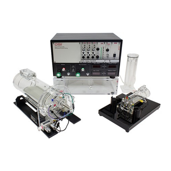
Page 14: System Hardware
System Hardware This chapter contains information on the hardware components of the system, including how to connect the hardware, and definitions and descriptions of the hardware. PFT Controller Pressure Panel PFT controller pressure panel The PFT controller pressure panel consists of: •... -
Page 15: Pressure Panel Front
Pressure Panel Front Pressure panel controls The following are descriptions and operational definitions of controls and modules on the front of the Pressure Panel 1. Preamplifier modules (Flow, Mouth Pressure, Esophageal) - These modules provide signal amplification and conditioning for the flow, mouth pressure, and (optionally) esophageal pressure transducers. 2. - Page 16 5. Large Animal/Small Animal mode selection switch – Toggles between the large animal and small animal flow vale adjustment control knobs. A green indicator light will illuminate above the selected valve control knobs. The large green knobs control the large animal flow rates when the PFT Pressure Panel is connected to the large animal reservoir.
-
Page 17: Pressure Panel Back
Pressure Panel Back Connections on the back of the pressure panel The following are descriptions of the connections on the back of the Pressure Panel 1. USB Port - The USB port accepts a standard non-powered USB cable which is then connected to the PC. All data acquired from the controller, and all control commands (from the PC) are sent through this connection. -
Page 18: Pressure Reservoir
Pressure Reservoir Small animal pressure reservoir The pressure reservoir is divided into two sections, negative and positive. The positive reservoir is used to inflate the lungs at the configured inspiration flow rate. The negative reservoir section is used to slowly deflate the lungs at the configured slow expiration flow rate during PV tests, and to deflate the lungs as quickly as possible during FV tests. - Page 19 Small animal pressure reservoir Large animal pressure reservoir Page 19 Pulmonary Function Test • Publication 014181-001 Rev 02 • www.datasci.com ©2023 Data Sciences International...
-
Page 20: Compressed Air Source
DSI offers a low noise air compressor for sale. The models have varied over the years, so model specific details are not included in this manual. If you purchased your compressor from DSI, please see the manufacturers product manual that was included with you unit. - Page 21 The following is a schematic representation of the manifold (Note: T represents the mouth pressure transducer): On the endplate of the animal chamber, there are two more ports on either side of the manifold. One port accommodates a cannula that connects the Pulmonary pressure transducer to the animal. The other port is used to monitor Blood Pressure, but this is not part of any maneuver;...
-
Page 22: Manifold Types
Manifold Types Mouse Manifold The mouse manifold is used on mouse chambers only 1. FRC valve (the mouse manifold has two) 2. Fast expiration valve port (the valve is not mounted in the image above) 3. Slow expiration valve port 4. -
Page 23: Rat/Gp Manifold
Rat/GP Manifold The Rat/GP manifold is used for rat and guinea pig chambers 1. FRC valve 2. Fast expiration valve port 3. Slow expiration valve port 4. Inspiration valve port 5. Mouth pressure transducer port 6. Inlet for sampling gases (N, O2, etc.). This port is also used to calibrate the mouth pressure signal. 7. -
Page 24: Large Animal Manifold
Large Animal Manifold The Large Animal manifold is used for rabbit, ferret, and primate chambers 1. FRC valve 2. Fast expiration valve port 3. Slow expiration valve port 4. Inspiration valve port 5. Mouth pressure transducer port 6. Inlet for sampling gases (N, O2, etc.). This port is also used to calibrate the mouth pressure signal. 7. -
Page 25: Configuring The Hardware
Configuring the Hardware 1 - Front Panel Connections To connect the wiring and tubing, make the following connections to the front of the pressure panel: 1. Use the largest tube to connect the Fast Expiration quick disconnect port on the negative reservoir to the Fast Expiration valve on the manifold. -
Page 26: Rear Panel Connections
2. Connect the USB connector to a USB port on the computer. Avoid going through a USB hub (including the hub on the monitor) unless it is approved for use by DSI. 3. Connect tubing from the Slow Expiration quick disconnect on the rear of the Pressure Panel to the green input on the negative reservoir. -
Page 27: Compressed Air Source Connection
3 - Compressed Air Source Connection If you are using any chamber type other than the mouse chamber you must connect a compressed air source that delivers 40 PSI to 50 PSI of pressure to the pneumatic control valves on the manifold. If the pressure is higher than 60 PSI, the pneumatic valves will be damaged. -
Page 28: Setting Positive Pressure
4 - Setting Positive Pressure Use the 8-position knob labelled Positive Pressure on the Valve Control module to set the desired pressure level. For most situations, set this to 50. Confirm the new pressure by watching the Positive Pressure display. The displayed pressure is approximate so anything within 5% should be acceptable. -
Page 29: Setting Negative Pressure
5 - Setting Negative Pressure Use the 8-position knob labelled Negative Pressure on the Valve Control module to set the desired pressure level. For most situations, set this to 50. Confirm the new pressure by watching the Negative Pressure Display. The pressure is approximate so anything within 5% should be acceptable. -
Page 30: Setting Slow Expiration Flow
When you see the correct value displayed on the Inspiration Flow digital display, flip the Inspiration valve switch back to Auto. Then you have successfully set the Inspiratory flow rate. Use the table below to estimate inspiration flow rates. Divide the subject’s TLC by the number of seconds required for the expiration. -
Page 31: Mouse Chamber Configuration Notes
Mouse Chamber Configuration Notes Several additional steps are required to configure the mouse chamber 1. Connect the Fast Flow valve to the mouse manifold port and to the Fast Expiration port on the negative pressure reservoir. 2. Connect the black cables with the ¼” jacks to the power and heater ports on the side of the chamber table. Page 31 Pulmonary Function Test •... - Page 32 3. Connect the pressure transducer and the solenoid cables to the ports on side of the chamber table. Page 32 Pulmonary Function Test • Publication 014181-001 Rev 02 • www.datasci.com ©2023 Data Sciences International...
-
Page 33: Switching Between Mouse And Rat
Switching Between Mouse and Rat It is common to purchase a Pressure Panel and both a plethysmograph for rat and a plethysmograph for mouse. The two work almost identically, except you are required to adjust a jumper on the Signal Generator module when you switch from using one plethysmograph to using the other. -
Page 34: Measuring Dead Space In The Manifold
Measuring Dead Space in the Manifold In the FRC test, the Pressure and Volume changes caused by the animal’s attempts to breathe help us derive the entire volume occluded from atmosphere. This volume is made up of the animal’s lung volume at the time of the occlusion plus the dead space. -
Page 35: Alternate Boyle's Law Method Without P
sure your V reflects what you injected. injected • Be sure to specify P in cm H O units—it should be somewhere near 1030 cm H Alternate Boyle’s Law Method Without P If P is not known, you can use this method to measure the dead space. This method requires you to make two injections, and to find two ΔP values. -
Page 36: Pressure Conversions And Useful Information
Find the difference from that stable value to the pressure before you injected the syringe. Use this difference as ΔP in the equation below. ∆���� × ���� ������������������������������������ = ���� ∆���� − ∆���� Pressure Conversions and Useful Information Conversion Multiply by this value Inches Mercury to cm H2O 34.53 Torr to cm H2O... -
Page 37: Hardware Configuration In Finepointe Control Panel
Hardware Configuration in FinePointe Control Panel To setup the software, you need to create a hardware configuration in the FinePointe Control Panel. The hardware configuration will appear as a station from within FinePointe. This only needs to be done once. The hardware configuration tells the system how the hardware is setup and what species you intend to run. - Page 38 The Login Name and Password must be an administrator of this computer (not necessarily the user who logged in at the start of this Windows session). If you are on a network, you may have to explicitly specify the network domain where the Login Name can be found.
- Page 39 Click the Hardware Configuration button to add the hardware configuration. The upper portion of the Hardware Configuration Page. Shown here, no Hardware Configurations have been created yet (so the list is empty). Click the New Configuration button to start the Create New Configuration wizard. The first page of the Create New Configuration wizard.
- Page 40 On this page you define the Site for your new PFT station. Site is a term used throughout the software which refers to all the collection apparatus associated with the data collection of a single subject. A Pressure Panel can be associated with no more than one PFT site. So here you will only put down as many sites as you have Pressure Panels (typically 1).
- Page 41 Pictured above a connection is made from Pleural Pressure to Lead 4. Most systems are not sold with this option. If your system was NOT sold with it, do not connect this lead, and simply leave the Pleural Pressure Lead on the Site disconnected.
-
Page 42: System Calibration
System Calibration To calibrate the PFT signals, you need to calibrate 2 or 3 transducers. These include flow, mouth pressure, and (optionally) pleural pressure. The flow transducer requires 3 separate calibrations since it appears on 3 leads, each lead at a different sensitivity: High Flow, Flow, and FRC Flow. You should calibrate once at the start of each day you intend to use the system. -
Page 43: Calibration Procedure
Calibration Procedure 1 - Open the Calibration Window To calibrate, bring up the Laboratory page in FinePointe Review. The area on the right is where you see icons for the stations. As shown here, there is one station icon named PFT Station. - Page 44 This picture shows the main calibration page for a PFT Station before it has been calibrated. Once calibrated, the "Last Calibration" will indicate when the signal was last calibrated, and the "Effective Range" will indicate the last effective range determined during calibration. When you calibrate, it is important that the flow calibrations be performed in the order presented on the calibration page.
-
Page 45: Calibrate Flows
2 - Calibrate Flows Before you begin calibrating the flows, place a luer plug in the tracheal port to ensure the manifold is isolated from the chamber. Begin by calibrating FRC Flow. Click the Calibrate button for FRC Flow. The calibration wizard begins at step 2 “Balance the Transducer”. As with all wizards in FinePointe software, the list at the left shows you the steps you will need to complete in order to finish the wizard, indicating which step you are on by the blue arrow. - Page 46 When you hit Next, the FinePointe software checks the waveform to determine if you have followed the instructions. Any warnings are indicated below the chart as shown in the following screenshot. In this example, the instructions say you must turn the Balance screw until the voltage is at zero. FinePointe checked and the signal is too high (it is 0.693V).
- Page 47 This time, FinePointe wants you to turn the zero knob until the signal is 0 volts. Do so and click Next. Page 47 Pulmonary Function Test • Publication 014181-001 Rev 02 • www.datasci.com ©2023 Data Sciences International...
- Page 48 In this step, you must inject 0.5mL into the chamber. Use the 1mL syringe and inject the 0.5mL volume fast enough, but without exceeding ±5volts on the chart. This may take some practice and you can repeat it as many times as you want. Before you deliver the volume, make sure the entire chart is at zero.
- Page 49 When you look at the frozen screen like this, you should go through the following check list: Is the entire injection captured? As shown above it clearly is. You can see this because the signal starts at zero, rises, and then returns to zero.
-
Page 50: Calibrate Pressure
3 - Calibrate Pressure Before you begin, put a luer plug in the tracheal port. Attach the calibrator tubing and a 10 mL syringe to a luer T, then attach the luer T to the N 2 Sample port. You will need this so that you can push air into the manifold and the calibrator simultaneously. Click the Calibrate button for Lung Pressure. - Page 51 Next switch to the DC Adj switch position on the preamplifier and turn the zero knob to zero volts. If it is close to zero, just click Next. If FinePointe accepts it and goes to the next step, then you are close enough, otherwise it will warn you are described above in the Flow calibration.
- Page 52 Turn on the FRC Valve to close off the manifold, and then force the plunger of the syringe down until the calibrator is at 20cm H At this point, the voltage should not drift down. If it drifts down, then you have a leak, and you should identify and fix the leak in the manifold.
-
Page 53: Creating A Pft Study
Creating a PFT Study To create a PFT Study, start at the Home page in FinePointe Review. Click the FinePointe → PFT Study button under Create study Options. Give your study a descriptive name and select the species you intend to acquire. Click Next. This page allows you to provide some descriptive information about the study. - Page 54 On this page you can fill in some specifics about how you want to collect data. Generally speaking, we recommend you save the tidal breathing for the end (after you perform the tests). This way the subject is fresh for the FRC tests.
- Page 55 Once you click finish, FinePointe creates the study database and opens the study. The image below shows what an empty study will look like. The study page has a command bar across the top. This bar has buttons which allow you to access forms and other pages within the study.
-
Page 56: Acquiring Data
Acquiring Data When you acquire data, you will find that the actual acquisition of the data takes very little time. The key to consistency and validity of the data is how you manage the subject within the apparatus. One factor which determines much of what you do is the dead space in the system. - Page 57 To launch acquisition from the Study page, open the study you want to acquire data to, and select Launch Station button on the command bar of the Study page. After you launch acquisition, FinePointe Station opens to the Assign Subject IDs page. In this page you identify the subject in the PFT chamber.
- Page 58 Make sure this content is filled in. You can change it later, but it needs to be filled in now. The Assign Subjects page provides a flexible way to associate a subject ID with this recording. In this page, you can create a new subject ID or use an ID which has already been created in the study.
- Page 59 You can easily change the view by selecting a view you feel is suitable under the View menu. For this description, the view second from the left is chosen. After you select the view, FinePointe Station reconfigures the display as follows: FinePointe Stations remembers the last view you selected so next time you run, you will not need to do this.
-
Page 60: Loading The Subject
Loading the subject At this point, you are ready to load the subject. Here is a suggested procedure: Make sure the FRC valve is off - in Auto Position - to open the manifold to the atmosphere. Make sure the Inspiration valve is on to bring fresh air in the manifold and clear CO2 build up Other switches on the Pressure Panel should be in the Auto position Connect the subject’s tracheal tube to the manifold inside the chamber Make sure that there is no leak around the trachea. -
Page 61: Saving Your Data
Saving Your Data After you complete the task sequence, exit FinePointe Station (File->End Session) and be sure to leave the box checked to save the data to the study. Note that any unchecked recordings are deleted and not saved to the study. Once you have made your selection, click Next. -
Page 62: Reports
Reports The reporting capabilities built into FinePointe are designed to provide a convenient means to quickly combine subjects into treatment groups and summarize your data. Since the report processing is automated, you can see your results almost immediately. To fully understand how the reporting works within FinePointe, you need to understand some simple concepts. - Page 63 The page shown above shows how the subject and group content is arranged. The left side of the display is divided into 2 lists: groups and subjects. The groups list shows you the groups which are currently created. You can modify or delete each of them by clicking the appropriate button under Modify or Delete header. The content on the right of the page changes based on what is selected on the left.
-
Page 64: Creating Reports
Creating Reports There are several kinds of report you can produce within FinePointe. From the study page, you pull down the button named Create Report and select the type of report you want to create. The Parameter Summary report summarizes a parameter (or formula). In addition to that report, you can also produce group average Flow- Volume or Pressure-Volume curves. - Page 65 Alternatively, you can select Other and then select one of the other parameters or an algebraic combination of them. Click Next. And lastly, select which subject groups to summarize in this report. You can also set the order that the groups are ▲...
-
Page 66: Modifying Measurements
Reports can be modified via the Modify Report Wizard. Reports can be exported to several different formats. Modifying Measurements If you choose not to use the automation of the tests, and run them manually, you will need to place the measurements in the recordings yourself. - Page 67 Select the recordings you want to adjust or create measurements on. When you do, trends are plotted in the area on the right for each recording you select. It will not be practical to select more than 4 at a time since the trend will probably get too small.
- Page 68 When you select a recording, any measurements that have already been placed will appear as shaded blue regions. If there is not any (as shown in the previous image), you will see no such region. In this case, you can place a measurement by clicking and dragging a region, then right click on that region to Place Measurement.
-
Page 69: Rejecting Data
Rejecting Data You can reject data in much the same way that you place a measurement. You select the region you want excluded from reporting. Then you right click on that region and select the Reject Data content menu option. This way to reject data is convenient for continuously monitored data but may not be so good for a PFT test. -
Page 70: Frc
The FRC tests measures the FRC lung volume by using Boyle’s Law. FRC lung volume is the Functional Residual Capacity. This is the volume of air that remains in the lung at the end of a normal expiration. This lung volume is important because by knowing this lung volume, it is easy to know all the other lung volumes. -
Page 71: Fast Flow Volume
Fast Flow Volume The FV test provides information about the dynamic lung properties. Dynamic lung properties are described by the flow-volume relationship of the lung. The Flow-Volume curve shows the flow at a given expired volume. Since the pressure across the lung is essentially constant during the acquisition of the flow-volume data, the flow value is proportional to the conductance of the limiting airways at a given expired volume. -
Page 72: Resistance & Compliance
Resistance & Compliance The resistance and compliance analysis produce the following: Parameter Description Units respiratory Rate Tidal volume (volume inhaled) Minute volume (the rate of ventilation) mL/min lung resistance O/mL/s Cdyn Dynamic compliance mL/cmH Cstatic Static compliance (Optional with special ventilation) mL/cmH dPpl Compliant pressure, pressure change from the start to the end of... -
Page 73: Appendix A - Troubleshooting
Appendix A - Troubleshooting This section provides general information that may help you resolve common user questions or problems. If you require additional assistance, please contact DSI Technical Support or email support@datasci.com. Common Reasons PFT Tests Might Fail This section lists the most common reasons the FRC, PV, and FV tests fail FRC Test •... -
Page 74: Fv Test
FV Test The inspiration to 30 cm H20 phase of the FV test is not triggered • This can happen if the end of the breaths cannot be determined during the breath history phase. The slow expiration phase is triggered when the breath hold phase ends. Make sure the calibration is good for all leads. -
Page 75: Test For Leaks In The Main Chamber
Start with the Slow Expiration, then Inflation, etc. If you cannot solve your leak problem, then you may have a faulty valve or transducer. Please call your DSI representative in that situation. -
Page 76: Animal Breathes During Tests
Animal Breathes During Tests If your animal is breathing throughout the tests, consider the following possibilities: • Inspiratory Flow Rate is too low. • Expiratory Flow Rate is too low. • Anesthesia dose should be increased. Page 76 Pulmonary Function Test • Publication 014181-001 Rev 02 • www.datasci.com ©2023 Data Sciences International... -
Page 77: Appendix B - Anesthesia
Appendix B – Anesthesia The following is a list of suggestions for anesthetizing an animal. First Choice For Guinea Pig, Rat, and Mouse, choose the following: Ketamine (50 mg/kg) + Medetomidine (0.33 mg/kg) combo Delivery : i.p. 1 mL/kg For example: 10 mL of 1 mg/mL Medetomidine 15 mL of 100 mg/mL Ketamine 5 mL water FI... -
Page 78: Second Choice
Second Choice Thiopentone sodium 100 mg/kg. Delivery: i.p. 1 mL/kg Third Choice Nembutal (50 mg/mL solution of Pentobarbital) Delivery: i.p. 0.8 mL/kg Notes • Pentobarbital is ok but you will get some of them breathing as you perform the test; you just have to be patient. Thiopentone tends to be better. -
Page 79: Appendix C - Interpretations Pft Results
Appendix C - Interpretations PFT Results This appendix describes things you should look for when you review results from the Pulmonary Maneuvers. While some things you look for only apply to a given test, many of them apply to all the tests. Overall, the passing of time will affect all tests. -
Page 80: Frc (Functional Residual Capacity) Test
FRC (Functional Residual Capacity) Test For the FRC test to successfully return good data, FinePointe must occlude the subject at the end of expiration (at FRC). In addition, the subject must attempt to breathe while its airway is occluded. Finally, there can be no leaks in the manifold. -
Page 81: No Efforts During Frc Occlusion
No Efforts During FRC Occlusion If you ventilate the subject prior to running the FRC test, it is possible that when FinePointe occludes the airway, the subject is hyperventilated and does not try to breathe. The data returned may look something like the following: The volume appears to drift away. -
Page 82: Pv (Pressure Volume) Test
PV (Pressure Volume) Test In this test, you need to watch out for a few things: • The flow was properly zeroed during calibration. • The expiratory duration is long enough and without attempts from the subject to breathe on its own. •... -
Page 83: At Tlc, Volume Drops As Pressure Falls
At TLC, Volume Drops as Pressure Falls If the pressure drop is accompanied with a slight decrease in the volume, then the air has escaped from the trachea directly to atmosphere. This can only be due to a leak in the manifold, and most probably one of the following: •... -
Page 84: Overlays Of Consecutive Pv Tests Differ
• Consider increasing the inspiratory flow to shorten the inspiration. • Consider ventilating the subject prior to running this test. • Consider adjusting (increasing) the anesthesia. Overlays of Consecutive PV Tests Differ When you are looking at PFT test results, you can select multiple rows in the PV table to overlay their results as illustrated below: One test for repeatability of data is to overlay 2 consecutive tests. -
Page 85: Fv (Flow Volume) Test
FV (Flow Volume) Test With this test, more than any other, you should be concerned about the position and comfort of the animal. Ripples or Squiggles Near the End of the Flow-Volume Curve If you observe squiggles near the end of the Flow Volume curve, it is probably because there is mucus, goo, or condensation in the lung or trach tube. -
Page 86: Appendix D - Suggested Reading
Appendix D - Suggested Reading This list of selected studies is recommended reading in the field of Pulmonary Maneuvers and may provide information beneficial to your own research. DuBois, Arthur B., Stell Y. Botelho, George N. Bedell, Robert Marshall, Julius H. Comroe, Jr. A rapid plethysmographic method for measuring thoracic gas volume: A comparison with nitrogen washout method for measuring functional residual capacity in normal subjects. -
Page 87: Contact Information
We are available to help you with your questions and concerns. Should you hit a roadblock or need some additional training, please feel free to visit the DSI Support Center at https://support.datasci.com to find articles and helpful information in our knowledge base, Chat with an agent, or setup time to receive one-on-one consultation. We are happy to help! DSI Technical Support—North America...
Need help?
Do you have a question about the Buxco FinePointe and is the answer not in the manual?
Questions and answers