Advertisement
Table of Contents
- 1 Safety Symbols
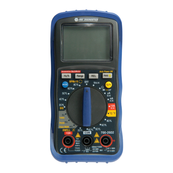
- 2 Controls and Jacks
- 3 Symbols and Annunciators
- 4 Specifications
- 5 Dwell Angle
- 6 Operation
- 7 Mode Button
- 8 Range Button
- 9 Data Hold / Backlight Button
- 10 Frequency or Duty Cycle Measurements
- 11 Temperature Measurements
- 12 Replacing the Battery
- 13 Replacing the Fuses
- 14 Battery Installation
- 15 Warranty Information
- Download this manual
AUTOMOTIVE DIGITAL MULTIMETER
Model BK 700-2602
INSTRUCTION MANUAL
¦ ¸
17
SAFETY INFORMATION
The following safety information must be observed to insure
maximum personal safety during the operation of this meter:
Do not use the meter if the meter or test leads look
damaged, or if you suspect that the meter is not operating
properly.
Never ground yourself when taking electrical measurements.
Do not touch exposed metal pipes, outlets, fixtures, etc.,
which might be at ground potential. Keep your body isolated
from ground by using dry clothing, rubber shoes, rubber
mats, or any approved insulating material.
Turn off power to the circuit under test before cutting,
unsoldering, or breaking the circuit. Small amounts of
current can be dangerous.
Use caution when working above 60V dc or 30V ac rms.
Such voltages pose a shock hazard.
When using the probes, keep your fingers behind the finger
guards on the probes.
Measuring voltages which exceed the limits of the
multimeter may damage the meter and expose the operator
to a shock hazard.
Always recognize the meter voltage
limits as stated on the front of the meter.
18
Advertisement
Table of Contents

Related Manuals for Napa BK 700-2602

Summary of Contents for Napa BK 700-2602
- Page 1 Do not use the meter if the meter or test leads look AUTOMOTIVE DIGITAL MULTIMETER damaged, or if you suspect that the meter is not operating Model BK 700-2602 properly. Never ground yourself when taking electrical measurements. INSTRUCTION MANUAL Do not touch exposed metal pipes, outlets, fixtures, etc.,...
-
Page 2: Safety Symbols
Never apply voltage or current to the meter which exceeds may result in damage to the product. the specified maximum: This symbol advises the user that the Input Limits terminal(s) so marked must not be connected 500V Function Maximum Input to a circuit point at which the voltage with V DC or V AC 1000V DC, 750V AC... -
Page 3: Symbols And Annunciators
Large 4000 count Liquid Crystal SYMBOLS AND ANNUNCIATORS Display with symbolic signs. Continuity Function switch Low Battery Positive (+) input jack for Diode DC/AC Voltage, DC/AC DATA HOLD Data Hold μ A /mA current, Hz/%duty AUTO Auto-Ranging cycle, Ohms, Diode, Alternating Current or Voltage Continuity, Capacitance, Direct Current or Voltage... -
Page 4: Dwell Angle
8CYL 0~45.0° 15 minutes of inactivity. +2.5% of rdg + 4 dgts Operating environment: 0 o C to 50 o C (32 o F to 122 o F) at < 70 % relative humidity. Overload protection: 250V dc or ac rms. Storage temperature: -20 o C to 60 o C (-4 o F to 140 o F) DC Voltage (Auto-ranging) at <... - Page 5 400.0uA 0.1uA ±1.0% of rdg±3 dgts 4.000MΩ 1kΩ 4000uA 40.00MΩ 10kΩ ±2.0% of rdg±3 dgts 40.00mA 10uA ±1.5% of rdg±3 dgts Input Protection: 250V dc or 250V ac rms. 400.0mA 100uA ±2.5% of rdg±5 dgts Capacitance (Auto-ranging) 10mA Range Resolution Accuracy Overload Protection: 0.5A / 250V and 10A / 250V Fuse.
-
Page 6: Operation
OPERATION Frequency width: 5Hz – 150kHz Sensitivity: <0.5V RMS WARNING: Risk of electrocution. High-voltage circuits, Overload protection: 250V dc or ac rms. both AC and DC, are very dangerous and should be measured with great care. Period Range Resolution Accuracy ALWAYS turn the function switch to the OFF position 2.0~ 20.0ms 0.1ms... -
Page 7: Data Hold / Backlight Button
measurements being made and is generally the best mode for Press BACKLIGHT button 2 seconds again to exit the light most measurements. For measurement situations requiring that mode. RELATIVE BUTTON a range be manually selected, perform the following: The relative measurement feature allows you to make 1. - Page 8 40V, 400V ≥6.5V rms 5Hz~20kHz AC OR DC CURRENT MEASUREMENTS ≥12V rms 5Hz~200kHz 1000V/750V ≥420V rms 50Hz~1kHz CAUTION: Do not make current measurements on the 400mA ≥45mA rms 5Hz~5kHz 10A scale for longer than 30 seconds every 15 minutes. ≥4A rms 5Hz~1kHz Exceeding 30 seconds may cause damage to the meter Note: The above data is only for reference.
-
Page 9: Frequency Or Duty Cycle Measurements
jack and the red test lead banana plug into the Positive + Press the Hz/% button to select “Hz” or “%”. Touch the test probes to the circuit under test and read the jack. frequency or duty cycle on the display. Turn the rotary switch to the Ω... - Page 10 Turn the rotary switch to the Period ms position. Fig.4 3. Connect the black test probe to ground and connect the red test probe to the signal wire that connects to the component to be measured. RPM (TACH) MEASUREMENTS Insert the black test lead banana plug into the Negative COM jack and the red test lead banana plug into the Positive + jack.
-
Page 11: Replacing The Battery
NOTE: Only traditional ignition systems with BREAKER POINTS 1. Disconnect the test leads from the meter. need to test the DWELL ANGLE. If the car has an ELECTRONIC Open the battery door by loosening the screws using a IGNITION SYSTEM, there is no need to test. Phillips head screwdriver. -
Page 12: Warranty Information
1603. Out of warranty repairs billable to the end user. For warranty and service coverage after YEAR ONE please call 888-227-1603. Technical Hotline: 888-227-1603 REPAIRS: MAIL TESTER FREIGHT PREPAID TO: NAPA For any technical assistance or possible service issues, Meter Repairs, 139 Elizabeth Ln., Genoa City, WI 53128... - Page 13 NOTE: RETURNS AUTHORIZATION and BRIEF DESCRIPTION OF PROBLEM MUST ACCOMPANY ALL REPAIR RETURNS...
Need help?
Do you have a question about the BK 700-2602 and is the answer not in the manual?
Questions and answers