Advertisement
Quick Links
Advertisement

Subscribe to Our Youtube Channel
Summary of Contents for VIVA FITNESS KH 325
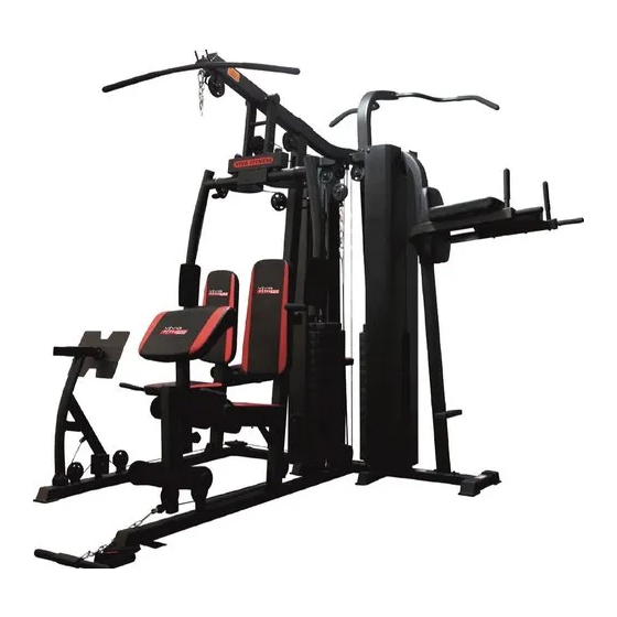
- Page 1 Installation and Operation Manual Deluxe Integrated Training Machine KH 325...
-
Page 2: Table Of Contents
Catalogue Safety knowledge..................1 Exploded view..................2-4 Parts list....................5-8 Installation steps...................9-34 Training instruction..................35 Directive drawing of training..............36-37 Warning....................37`... -
Page 3: Safety Knowledge
Safety knowledge Please keep this instruction manual properly for reference in the future. Precautions Although the training equipment has taken the safety precautions into consideration as much as possible during the design and manufacturing process, there are still some safety precautions which needs to be observed during the operation. -
Page 4: Exploded View
2780mm 2650mm Exploded view... - Page 5 Attachment B...
- Page 6 Attachment C...
-
Page 7: Parts List
Parts list Main Parts A Name and Quantit Serial Name and Quantit specificatio numbe specificatio Serial numbe Rear bottom pipe 50 internal plug of assembly the square tube Ground pipe 25 circular tube assembly plug Front ground pipe 50 internal plug of assembly the round tube Pedal... - Page 8 (M10*20) Rotating U seat Hexagonal bolt (M10*135) sponge holder Hexagonal bolt tube (M10*90) Iron net protection Hexagonal bolt cover (M10*65) High handlebar Hexagonal bolt tube assembly (M10*45) high-pulling Hexagonal bolt handlebar (M10*20) assembly Swing arm U- Hexagon socket shaped seat pan-headed bolt assembly (M10*12)
- Page 9 50*70 internal plug of the rectangular tube 25*50 internal plug of the rectangular tube Tool Spanner 13#,14# Hex wrenches 6# and 17# Special spanner B Parts list Serial Name and Quantit Serial Name and Quantit numbe specificatio numbe specificatio Hexagonal bolt parallel bars' lower (M8*95) support frame...
- Page 10 (M10*90) Pan head square 25 circular tube plug neck bolt (M10*70) Hexagonal bolt Hexagonal bolt (M8*65) (M8*80) Hexagonal bolt Jam nut(M8) (M8*25) C Parts list leg curling bottom Rotation shaft tube weldment Connection pipe Pulley pressing weldment sleeve (small) Pulley frame Hexagonal bolt (M10*95) Backrest cushion...
-
Page 11: Installation Steps
Installation steps Installation steps of main part A IMPORTANT: Please check whether all the accessories are complete after opening the carton. Remarks: During the assembly process, it is best to assemble the product by two or more people together so as to avoid injury during the assembly process. - Page 12 Step 2 1. Place the front inclined pipe assembly (6) on the assembled ground pipe assembly (2) in accordance with the picture, use M10*65 pan head square neck bolts (71), Φ10 flat pads (87) and M10 jam nut (85) to fasten them tightly.
- Page 13 Step 3 1. First install the shock pad (44) and clump weight (31) into the counterweight guide rod weldment (5) in accordance with the picture; then insert them in the direction in accordance with the picture, and pass the straight pin (62) through the Counterweight head bushing (48) and the first hole of the weight lever assembly (10) (counting from top to bottom), and then install the counter weight head (30);...
- Page 14 Step 4 1. Align the holes on the horizontal tube on the carrying bar assembly (12) with the counterweight guide rod weldment (5) and assemble; then use M10*20 hexagonal bolt (77), Φ10 flat pads (87) and shield connecting plate 1 (9) to fasten from the top, but not fasten tightly temporarily;...
- Page 15 Step 5 1. Place the limit pipe assembly (14), front inclined pipe assembly (6), U-shaped seat connecting pipe assembly (15) in accordance with the picture, and use M10*95 hexagonal bolts (90), M10*90 hexagonal bolt (74), Φ10 flat pad (87) and M10 jam nut (85) to tighten it. 2.
- Page 16 Step 6 1. Insert the rotation shaft (67) into the front bottom frame support pipe assemble (7) in accordance with the picture, and then align the leg-lifting assembly (16) with the front bottom frame support pipe assemble (7) in accordance with the picture, and use M10 *20 hexagon socket pan-headed bolts (72) and Φ10 flat pad (87) to fasten tightly.
- Page 18 Step 8 1. Take the wire ropes (32) and place them as shown in the picture. Assemble them in the sequence shown in the picture. 2. The assembly methods of pulleys A, B and D are the same, which are as shown in the picture. The sequence is M10*65 hexagonal bolt (75), pulley assembly (46), M10 jam nut (85);...
- Page 19 Step 9 1. Take the wire ropes (32), place them as shown in the picture, and assemble them in the order shown in the picture. 2. As shown in picture A, the sequence is M10*65 hexagonal bolt (75), pulley assembly (46), M10 jam nut (85), which are fixed in the front inclined pipe assembly (6);...
- Page 20 Step 10 1. Take the butterfly arm wire ropes (33), place them as shown in the picture, and assemble them in the sequence shown in the picture; 2. As shown in pictures A and E, hang both ends of the wire rope (33) in the right swing arm assembly (18) and left swing arm assembly (20);...
- Page 21 Step11 1. Take the wire ropes (32), place them as shown in the picture, and assemble them in the sequence shown in the picture; 2. As shown in picture A, the sequence is M10*45 hexagonal bolt (76), Φ10 flat pad (87), pulley assembly (46), Φ10 flat pad (87) and M10 jam nut (85), which are fixed on the leg-lifting assembly (16);...
- Page 22 Step 12 1. Take the backrest cushion component (35), fix it on the cushion adjustment tube (93) with M8*40 hexagonal bolts (79) and Ф8 flat pad (88) in accordance with the position in the picture, and then fix the cushion adjustment tube (93) and insert it into the front inclined pipe assembly (6), and finally fasten it tightly with the spring pin rotary knob (43);...
- Page 23 Step13 1. Place the iron net protection cover (25) and the shield connecting plate2 (11) in accordance with the picture; fasten and fix them to the installed main part with M10*10 hexagon socket pan-headed bolts (78) and Φ10 flat pads (87).
- Page 24 Step14 1. Assemble the high handlebar tube assembly (26), eight-ring chain (66), lock catch (65), low-pulling handlebar assembly (27), training rope assembly (38), and nut cover (91) as shown in the picture; put the round adhesive tape components (39). 2. After the assembly is completed, check whether the screws are are fastened and fixed tightly.
- Page 25 Installation steps of attachment section B Step13 Note: Before you assemble Attachment B, you need to reassemble the body step 13 1. Place the weldments for connection pipe jacking (96) and carrying bar assembly (12) in accordance with the picture; use M10*90 Hexagonal bolt (74), Φ10 flat pads (87) and M10 jam nuts (85) to put them tightened and fixed;...
- Page 26 Step 1 1. Place the parallel bars parallel bars' lower support frame (1) and the rear bottom tube assembly (A-1) in accordance with the picture, and use M10*95 hexagonal bolts (19), Φ10 flat pads (27) and M10 jam nuts (30)to fasten them tightly. 2.
- Page 27 Step 2 1. Place parallel bars' upper support frame (2) and high-pulling handlebar assembly (3) of the double pole in accordance with the picture, and fasten and fix them with M10*20 hexagonal bolts (21) and Φ10 flat pads (27). STEP2 21 27...
- Page 28 Step3 1. Place the parallel bars' left armrest tube (4), parallel bars' right armrest tube(5) and parallel bars' upper support frame (2) in accordance with the picture, and use M10*75 hexagonal bolts (31), M10*20 hexagonal bolts (21), Φ10 flat pad (27) and M10 jam nut (30) to fasten and fix them, and finally assemble it with the inserted pin with suspension loop (18).
- Page 29 Step 4 1. Align parallel bars' upper support frame (2) with the holes of the backrest assembly (9) in accordance with the picture, and then fasten and fix them with M8*95 hexagonal bolts (26) and Φ8 flat pads (29). 2. Align the parallel bars' left armrest tube (4) and parallel bars' right armrest tube(5) with the holes of the rubber grip assembly for hands (10) in accordance with the picture, and then use M8*65 hexagonal bolts (24) and Φ8 flat pads (29) to fasten and fix them.
- Page 30 Step5 1. Place the assembled dumbbell stool main frame (32) and the parallel bars' lower support frame (1) in accordance with the picture, and use M10*70 pan head square neck bolts (23), Φ10 large flat pads (44) and torx knob nuts ( 37) to fasten and fix.
- Page 31 Installation steps of attachment section C Step 9 Note: Before you assemble Attachment C, you need to reassemble the body step 9 1. Take the wire ropes (97), place them as shown in the picture, and assemble them in the sequence shown in the picture.
- Page 32 Step 1 1. Place the leg curling bottom tube weldment (1) and the rear bottom pipe assembly (A-1) in accordance with the picture, use M10*90 hexagonal bolts (23), Φ10 flat pads (30) and M10 jam nuts (31) ) to fasten and fix them tightly. 2.
- Page 33 Step 2 1. Put the leg curling bottom tube weldment (1) and the backrest cushion frame (4) in accordance with the picture, and fasten and fix them with M10*95 hexagonal bolts (22), Φ10 flat pads (30) and M10 jam nuts (31). 2.
- Page 34 Step 3 1. Insert the rotating shaft (20) into the leg curling bottom tube weldment (1) in accordance with the picture, and then align the leg- lifting frame (8) with the leg curling bottom tube weldment (1) in accordance with the picture, and use M10*20 hexagon socket pan- headed bolt (27) and Φ10 flat pad (30) to fasten and fix.
- Page 35 Step4 1. Next, go on the assembly of the loaded leg press wire rope assembly (A-97) and do the job in the sequence shown in the picture; 2. As shown in picture A, the sequence is M10*45 hexagonal bolts (26), Φ10 flat pad (30), pulley assembly (12), Φ10 flat pad (30), M10 jam nut (31), which are fixed on the pulley frame (3);...
- Page 36 Step 5 1. Place the seat cushion frame (5), the right arm-rest frame (6) and the left arm-rest frame (7) in accordance with the picture, and use M10*70 hexagonal bolts (24), Φ10 flat pads (30) and M10 jam nuts (31) to fasten and fix them tightly. 2. Take the seat cushion assembly (10) and fasten and fix it with M8*65 hexagonal bolts (29) and Ф8 flat pads (32) in accordance with the position in the picture;...
-
Page 37: Training Instruction
Training instruction In addition to the functions of enhancing physical fitness and building muscle, this product also plays a role in weight loss through a reasonable diet. Warm up before training The warm-up exercise at this stage can enhance the blood circulation of the trainers' bodies and make the muscles reach a good training state, while reducing the risk of cramps or muscle damage during the process of training. -
Page 38: Directive Drawing Of Training
Directive drawing of training Bent-knee training (rectus abdominis) Install the low-pulling Seated rowing (trapezius muscle) “T-shaped” handlebar assembly at Biceps training (biceps-forearm Install the “T-shaped” low-pulling the lower pulley. Lie flat on the handlebar assembly at the lower muscles) Install the low-pulling T- ground, with your legs almost pulley, sit on the ground with your shaped handlebar assembly at the pulley,... -
Page 39: Warning
Straight arm pull-down (pectoralis Low-pulley training (triceps) major, deltoid muscles) Install the high- Chest- expansion training (pectoralis Install the high handlebar assembly at pulling T-shaped handlebar assembly at major) the high pulley, adjust the round sponge the high pulley, sit on the seat cushion, holder to the highest position, hold the Adjust PRE-STRETCH...
Need help?
Do you have a question about the KH 325 and is the answer not in the manual?
Questions and answers