Table of Contents
Advertisement
Quick Links
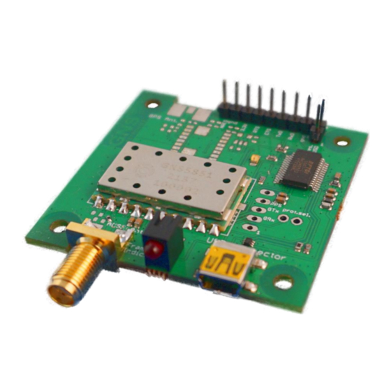
GNS 5851 StarterKit
Quick guide
confidential information
manual
The GNS 5851 StarterKit has been designed to support developers during
design-in of the GNS 5851 stand-alone module solution.
GNS Electronics GmbH
Adenauerstrasse 18
D – 52146 Würselen
Germany
www.gns-electronics.com
info@gns-electronics.com
1
V 0.9, 2021-09-28
Advertisement
Table of Contents

Related Manuals for GNS 5851 StarterKit


Summary of Contents for GNS 5851 StarterKit
- Page 1 GNS 5851 StarterKit Quick guide confidential information manual The GNS 5851 StarterKit has been designed to support developers during design-in of the GNS 5851 stand-alone module solution. GNS Electronics GmbH Adenauerstrasse 18 D – 52146 Würselen Germany www.gns-electronics.com info@gns-electronics.com V 0.9, 2021-09-28...
-
Page 2: Introduction
GNS 5851 StarterKit Features • Power supply via Mini-USB socket • Access to all signals of the GNS 5851 via pin header contacts. • PC data connection via the integrated USB to UART converter or direct access to the serial interface (3.3V) of the GNS 5851 for connection to other data processing devices. -
Page 3: Table Of Contents
Quick guide confidential information manual Index Introduction ..........................2 1 Description of the GNS 5851 StarterKit ................4 2 USB Driver Installation......................5 Windows 10 ........................5 Linux ..........................5 MacOS .......................... 5 3 GNS5851 StarterKit Board Layout ..................6 4 GNS5851 StarterKit Board Block Diagram ................ -
Page 4: Description Of The Gns 5851 Starterkit
• AIS VHF antenna • USB-Cable (USB-A to Mini-A) Since the GNS 5851 module has the same pinout as the GNS 5892R and GNS 5894T modules, they share a single StarterKit PCB design. Depending on the production batch, your board might be marked as GNS 5851, GNS 5892R, GNS 5894T or a combination thereof. -
Page 5: Usb Driver Installation
2 USB Driver Installation The GNS 5851 Starter kit features an FTDI USB-to-UART bridge which may need a manually installed driver to properly work. 2.1 Windows 10 If Windows does not recognize the FTDI bridge automatically, the appropriate driver needs to be installed manually. -
Page 6: Gns5851 Starterkit Board Layout
GNS 5851 StarterKit Quick guide confidential information manual 3 GNS5851 StarterKit Board Layout JP2: FTDI Reset JP1: direct access to open: FTDI active GNS5851 signals: closed: FTDI disabled, - TxD, RxD serial data can - NReset be accessed via FTDI Serial to... - Page 7 GNS 5851 StarterKit Quick guide confidential information manual UMPER AND ONNECTOR ESCRIPTION ONNECTOR IGNAL ESCRIPTION Direct access to GNS5851 UART. 1: GND UART I/O Voltage is 3.3V. 2: RxD (GNS5851 ser. input) 3: TxD (GNS5851 ser. output) 4: N.U. (marked CTS) 5: N.U.
-
Page 8: Gns5851 Starterkit Board Block Diagram
1. Connect the antenna to the GNS 5851 StarterKit 2. Connect the GNS 5851 StarterKit via USB to a Windows PC 3. After a few seconds the device is ready for use and is displayed in the device manager as "USB Serial Port"... -
Page 9: Gns5851 Starterkit Hardware
GNS 5851 StarterKit Quick guide confidential information manual 5 GNS5851 StarterKit Hardware 5.1 Assembly Drawing Top Side (with dimensions) V 0.9, 2021-09-28... -
Page 10: Gns 5851 Starterkit Schematic
GNS 5851 StarterKit Quick guide confidential information manual 5.2 GNS 5851 StarterKit Schematic V 0.9, 2021-09-28... -
Page 11: Pcb Layout
GNS 5851 StarterKit Quick guide confidential information manual 5.3 PCB Layout V 0.9, 2021-09-28... -
Page 12: Ordering Information
GNS 5851 StarterKit Quick guide confidential information manual 6 ORDERING INFORMATION Ordering information Type Part# Description GNS 5851 Starter Kit 4037735100077 7 RELATED DOCUMENTS Name Description Available from GNS5851_AIS_receiver_datasheet_0.9.pdf GNS 5851AIS Module Datasheet www.gns-electronics.de 8 DOCUMENT REVISION HISTORY V0.9 2021-09-28 C.
Need help?
Do you have a question about the 5851 StarterKit and is the answer not in the manual?
Questions and answers