Advertisement
Quick Links
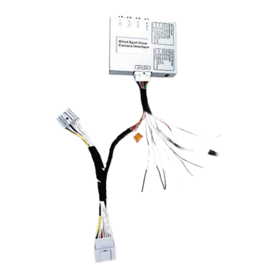
Product
t descriptio
n:
This 4‐Ca
mera Blind Sp
pot View Interf
surroun
d blind area w
while turning o
view or
phone mirror
device's video
Cars Sui
itable:
2016+ Mali
2
ibu which u
BSV G
GM7
Ins
stalla
ation
face (Front, Ri
ight, Left and
or reversing. It
ts inserter mo
o output onto
o the car scree
uses one‐pie
ece head un
th
his box can als
[]
The earlier car
T
Malibu, pl
ease check Fo
GVIF‐GM.
[]
M
Manual Version:
‐2016
6
man
ual
Product N
Name:BSV‐G
Rear Camera)
) can make th
he OE monitor
ode makes it ca
an insert DVR
or TV tuner o
en.
nit.
so fit into this
car if the inpu
ut harness got
types like 201
13~14 year's
osp sales team
m for the BSV‐
V
V20161019
GM7‐2016
display
or 360 bird
t changed.
Advertisement

Summary of Contents for BSV GM7-2016
- Page 1 V V20161019 Manual Version: BSV G ‐2016 6 stalla ation ual Product N Name:BSV‐G GM7‐2016 Product t descriptio n: This 4‐Ca mera Blind Sp pot View Interf face (Front, Ri ight, Left and Rear Camera) ) can make th he OE monitor display surroun d blind area w while turning o or reversing. It ts inserter mo ode makes it ca an insert DVR or TV tuner o or 360 bird view or phone mirror device’s video o output onto...
- Page 2 Part No. 1 1 Camera Int terface 2 1 Camera RC CA Harness 3 1 Switch key ypad 4 ‐ Optional ca amera's ava ailable. 1. Desc cription: The BSV‐G GM7‐2016 cam mera interface e is the latest line of produc ct from FOSP. It has 2 work‐ ‐modes, video o inserter mode and d Blind spot V iew mode. An nd all installati ion is done by inserting 1 co onnector1 beh hind the Head unit, which is very ea asy. ...
-
Page 3: Dip Settings
Max 3A outp ut for all came eras by giving a 12V out wh en camera vid deo is displaye ed. The installe ers just connect all ca amera’s powe er input to the “Reverse‐out t” wire. 2. DIP Settings: hen DI P8 of goes low w, this box goe es into BSV mo ode: DIP ON[Dow wn] Default 1 Right t camera insta alled (V1) Right cam era not install led WN(ON) 2 Left c camera install led (V2) Left came ra not installe ed ... - Page 4 Set DIP4 =DOWN t to say the trigg ger is from wir re, not can bu us. Then the insta aller can conne ect the wires t to 12V[turn lig ght] to manua ally force the display to tha t video inpu ut. When DIP P8 of goes Hig gh, this box go oes into Inserte er mode: DIP ON[Dow wn] Default 1 insta lled (V1) not install ed WN(ON) 2 insta lled (V2) not install ed WN(ON) 3 insta lled (V3) ...
- Page 5 The inpu ut switch whe en in Inserter r mode: e can wires an nd video wires s inside. (1) The u user can pres ss the Keypa d to switch. sert this harne ess between t the OE plug an nd (2) The K Keypad shou uld not be rem moved in onitor. BSV mode. he interface sh hould be set b y the DIPs firs st, then sert in. ...
- Page 6 5. Cam mera Conn ection: A All camera's w will be connect ted with the g green wire. It c can provide 12 2V/3A which i s sufficient to o supply power for the 3 or 4 camera a's. Power T The Camera’ G GND should no ot be connect ted, only red‐p power wire to Reverse‐out f for 12V. becau use the 】 ...
- Page 7 7. Para ameters: No. Name e Paramete er 1 Front Cam m Video , Rever rse Cam video o 0.7Vpp w with 75 ohm im mpedance NTSC/PA AL/SECAM aut omatic switch h 2 Reverse Co ontrol wire >5V will force into cam mera mode. 3 Normal Po ower consump ption 4.8W 4 Standby cu urrent < 10uA 5 Reverse tr igger threshol ld >5V trigg 6 ...
Need help?
Do you have a question about the GM7-2016 and is the answer not in the manual?
Questions and answers