Table of Contents

Related Manuals for Kessler-Ellis Products 532K

Summary of Contents for Kessler-Ellis Products 532K
- Page 1 532K Process Display Temperature display for J, K and N thermocouples Installation and Operating Manual KESSLER-ELLIS PRODUCTS 10 Industrial Way East Eatontown, NJ 07724 800-631-2165 • 732-649-7100 http://www.kep.com 99906 11/05/03...
-
Page 3: Table Of Contents
Summary Short description ............... 2 Safety instructions and warnings ........2 2.1 Use according to the intended purpose ..... 2 Mounting................3 3.1 Installation ..............3 3.2 Electrical connection ..........3 Start-up................3 Programming...............3 5.1 Switching to programming ........3 5.2 Changing the parameter setting ....... 4 5.3 Saving the parameter setting ........ -
Page 4: Short Description
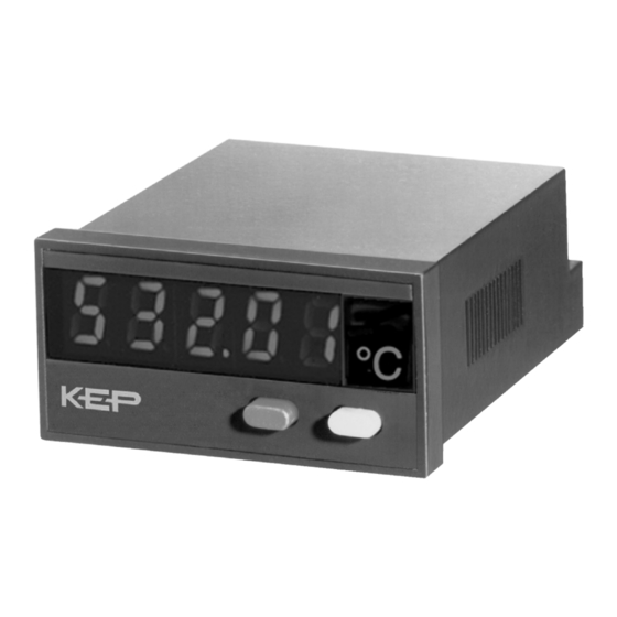
1 Short description This digital display is an easy-to-use, microprocessor- controlled device for the display (and the acquisition) of measured temperature values. The temperatures are measured by means of J, K and N thermoelectric cou- ple sensors. They can display either the current mea- sured value, the maximum value or the minimum value. -
Page 5: Mounting
Mounting 3.1 Installation 1. The digital display shall not be installed near to con- Important note: tactors or motor starters. Before carrying out any installation or maintenance 2. We recommend the use of wire end ferrules in order work, make sure that the power supply of the digital to avoid short-circuits between adjacent terminals. -
Page 6: Changing The Parameter Setting
Changing the parameter setting 1. press the right-hand/grey key to change the 4. set now the numerical value using the right- parameter setting by one value at a time hand/grey key ⇑ ⇑ 2. to input numerical values, select first the decade with 5. - Page 7 5.4.2 Reference point compensation (Continued) Reference point compensation Selection in the menu Internal reference point compensation External reference point compensation Adhere to point 5.4.2.1 5.4.2.1 External reference point temperature External reference point temperature Selection in the menu Input of the known value of the external reference point temperature in 0,1 °C/0,1 °F, according to the temperature unit set 5.4.3 Decimal point...
-
Page 8: Programming
5.4.6 Maximum value acquisition 5.4.6.1 Resetting the maximum value This allows defining whether the maximum value can The maximum value may be saved and consulted be reset during operation or not. However, the maxi- during operation (see 6.1) mum value can only be reset if the maximum value display is the active function (see 6.1). -
Page 9: Operation
Operation Switching the display during operation press the right-hand/grey key to select among the follo- time, the display switches to the following display func- wing functions: tion. This is confirmed by a 2-second display of the –current measured value designation of the new function. After these 2 seconds, –minimum value the display shows, depending on the selection, the –maximum value. -
Page 10: General Technical Features
Main technical features Operation: Display range: by means of two front panel keys (see temperature range), with leading zeros suppression Measuring range overflow, indica- DIsplay: ted by ooooo on the display. 5-digit display, red 7-segment LED’s, Measuring range underflow, indicated by uuuuu Height of the figures 8 mm on the display. -
Page 11: Environmental Conditions
Front panel for screw mounting, Panel cut-out 50 x 25 mm Operating temperature: Seal -20 °C ... +65 °C, relative humidity < 85% Multilingual operating instructions 1 set of self-adhesive symbols Storage temperature: -25 °C ... +70 °C Order code 532K... -
Page 12: Dimensions
Digital display dimensions Panel cut-out Mounting frame Panel cut-out Countersinking Af3, DIN 74...
Need help?
Do you have a question about the 532K and is the answer not in the manual?
Questions and answers