Advertisement
WARNING AGAINST COUNTERFEIT PRODUCTS
Always purchase from a Horizon Hobby, LLC authorized dealer to ensure authentic high-quality Spektrum product. Horizon Hobby, LLC disclaims all support and warranty with regards, but not limited to, compatibility and performance of counterfeit products or products claiming compatibility with DSM® or Spektrum technology.
 NOTICE: This product is only intended for use with unmanned, hobby-grade, remote-controlled vehicles and aircraft. Horizon Hobby disclaims all liability outside of the intended purpose and will not provide warranty service related thereto.
WARRANTY REGISTRATION:
Visit www.spektrumrc.com/registration today to register your product.
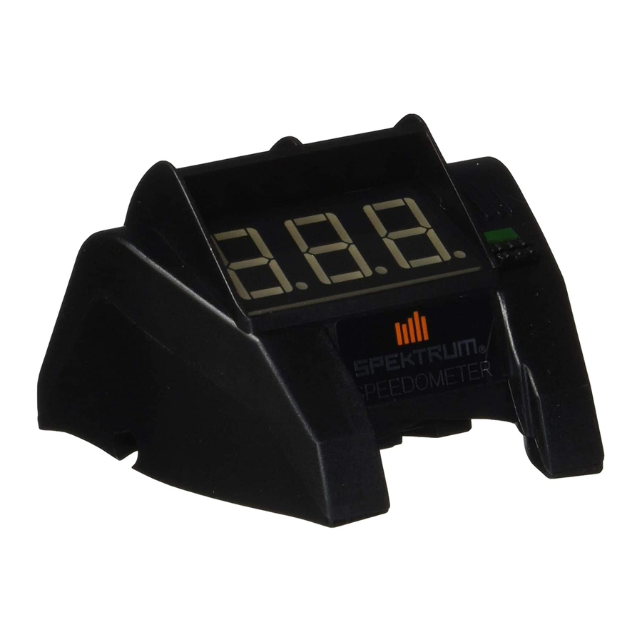
SPEKTRUM SPEEDOMETER MODULE (Spm6740)
The Spektrum Speedometer Module provides an easy to use, large format, reading of the vehicles speed on the Spektrum™ DX2E Transmitter. The Speedometer module can also be used to input roll-out and pole count.
")

Requires a telemetry module or a telemetry receiver and a brushless motor sensor.
SPEEDOMETER INSTALLATION
- Remove the screw installed in the DX2E transmitter case as shown.
![]()
- Remove the cover on the top of the radio using a small flat blade screw driver.
![]()
- Ensure the transmitter is turned off and then press the Speedometer Module into place and secure it with the screw removed in step 1.
![]()


BINDING
With the Speedometer Module installed, bind the transmitter to a telemetry capable receiver following the directions in the transmitter manual.
USING THE SPEEDOMETER MODULE
- The Speedometer Module will turn on/off with the transmitter.
- Once powered on, the Speedometer displays the Speedometer screen.
If there is no RPM telemetry data coming from the receiver (i.e. vehicle not moving) the module will display a moving ring around the digits. Once RPM telemetry data is received, the module will return to normal operation.
- Drive the vehicle. The calculated speed will be displayed in mph or kph depending on settings.
- Press the Push Button (longer than 2.5 seconds) to display the maximum speed logged this session (max speeds are erased once powered off). Once the button is released, the display will go back to the current speed.
If the speed is below 5kph (3.1 mph) the speed display will show 3 dashes "---" indicating the speed is too low to read.
SETUP MODE
Hold the Push Button down while booting up the Speedometer Module to enter Setup Mode.
- Units: "UN" will be displayed indicating the Unit value can be edited
- After about 2 seconds the display will read either EU (metric) or US (imperial).
- Short press (shorter than 1 second) the Push Button to switch between units.
- Once finished, Press the Push Button (longer than 2.5 seconds) to move to the next setting.
 Tip: The dot located at the bottom right of the screen is illuminated for EU (metric) and off for US (imperial).
Pole Count: "PC" will display, indicating Pole Count can be edited.
- After about 2 seconds the display will show an even pole count between 2 and 32.
- Press the Push Button (less than 2.5 seconds) to change the pole count by 2.
- Once finished, Press the Push Button (longer than 2.5 seconds) to move to the next setting.
- Roll Out: "RO" will display, indicating Roll Out can be edited.
- After about 2 seconds the current Roll Out settings will be displayed in values between 0.3–30.0cm (0.1–11.8in).
- The right most digit will blink, indicating it can be modified. Press the Push Button (less than 2.5 seconds) to change the digit from 0-9. Press the Push button (longer than 2.5 seconds) to change to the next digit to the left.
- Repeat for all digits.
- Once all digits are entered, the module will go back to the default Speedometer display.
| Vehicle | Rollout | Poll count |
| Losi Tenacity SCTE | 1.5 | 4 |
| Losi Ten SCTE/SCBE | 1.5 | 4 |
| Losi Ten-MT | 1.6 | 4 |
| Losi Baja Rey | 1.3 | 4 |
| Losi Rock Rey | 1.3 | 6 |
| Losi 8ight E RTR | 1.5 | 4 |
| Losi DBXL-E | 1.9 | 4 |
| Losi LST XXL2-E | 1.3 | 4 |
| ECX 2WD Torment BL | 1.5 | 4 |
| ECX 2WD Ruckus BL | 1.7 | 4 |
| ECX 4WD Ruckus BL | 1.4 | 4 |
MANUALLY CALCULATING ROLLOUT
Rollout is the distance a vehicle travels per one revolution of the motor. To calculate rollout choose a method bellow:
Method A:

- Using a marker, mark a reference line on the pinion gear.
- Set the car next to a ruler at 0 inches, then roll the car forward by hand. Count each revolution of the reference mark on the pinion. At exactly 10 revolutions stop the car.
- Measure the exact distance the car traveled in ten revolutions and divide this distance by 10 (e.g., 12.0" divided by 10 = 1.20").
Method B: Rollout = Tire Circumference divided by Spur Gear/Pinion ratio times internal drive ratio
- Find the tire circumference: Multiply the tire's diameter by 3.142(π). (e.g., 4.50 inch tire diameter x 3.142 = 14.14 inch Circumference).
- Spur Gear / Pinion Ratio: Divide the tooth count of the spur gear by the pinion gears tooth count (e.g., If the Spur is 40 and the pinion is 16, divide 40 by 16 = 2.5. The Spur to Pinion Ratio is 2.5:1).
- Internal Drive Ratio: The internal drive ratio of the vehicle (gear box reduction) is supplied by the manufacture specification. (e.g. 3.9:1).
- Final Drive Ratio: Multiply the Spur/Pinion ratio by the internal drive ratio to find the Final Drive Ratio (e.g., 2.5 x 3.9 = 9.75).
- Rollout: Use the tire circumference from STEP 1 and divide by the final drive ratio found in STEP 4 to find Rollout (e.g., 14.14 / 9.75 = 1.5 Rollout).

Documents / ResourcesDownload manual
Here you can download full pdf version of manual, it may contain additional safety instructions, warranty information, FCC rules, etc.
Download Horizon Hobby Spektrum SPM6740 - Speedometer Module For DX2E Transmitter Manual
Advertisement
Need help?
Do you have a question about the Spektrum SPM6740 and is the answer not in the manual?
Questions and answers