Advertisement
Quick Links
Thank you for choosing a NIVELCO instrument.
We are sure that you will be satisfied throughout its use.
1. APPLICATION
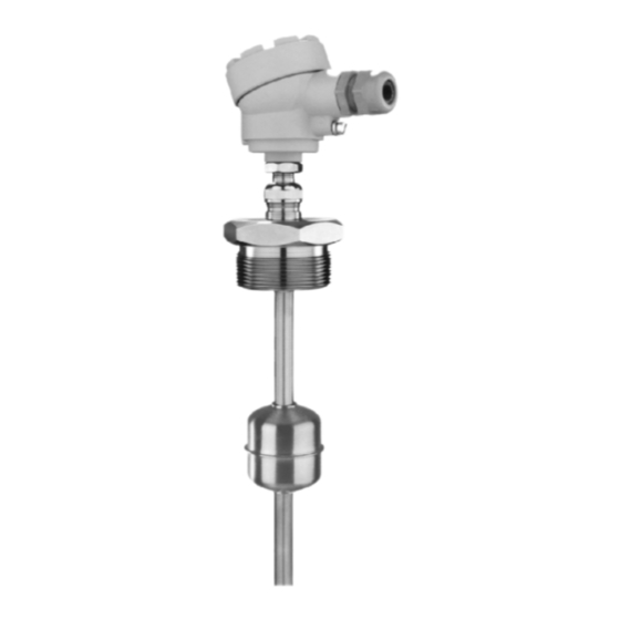
The interaction of the magnetic float and the reed relays (incorporated in the protection tube) is the basis of
the NIVOPOINT magnetic float level switch series operation. They are suitable for level indication of normal
and explosive liquids, and can be used for level control tasks. The protecting tube contains a max. of 5
relays. Parts of the instrument are: probe tube with magnetic float and housing containing the connection
terminal.
The magnetic float moves alongside the protection tube tracking the level of the liquid and activating the reed
relays. As the float passes a relay it changes the output state of the relay which retains this state latching
until the level decreases and the float moves again along the respective relay to switch its state back.
2. TECHNICAL DATA
2.1. G
ENERAL DATA
TYPE
MR
Insertion length
Stainless steel
Material of wetted parts
(1.4571 / BS 316Ti)
2.5 MPa (25 bar) at +20 °C
Max. process pressure
min. 0.8
Medium density
3
kg/dm
∅ 52x59mm
Nominal float
dimensions / shape
cylinder
-40 °C ... +150 °C
Medium temp. range
-40 °C ... +95 °C
Ambient temp. range
Output
Switching rate
Switch differential
Distance of switches
Electrical connection
1", 1½", 2" BSP
Process connection
1", 1½", 2" NPT
Sealing material
Klingerit 400
Electrical protection
Ingress protection
Ex marking
Dimension of the hous.
Mass
* dimensions of the float depend on the order
Note: the device must be installed with Ex d IIC certified explosion-proof cable gland.
2.2. A
E
DDITIONAL DATA FOR
X APPROVED MODELS
C
LASS
Max. ambient temperature from –40 °C
Max. medium temperature from –40 °C
2.4. O
C
RDER
ODE
T
YPE
Standard
Standard / plastic
coating and float
Notes:
** The order code of an Ex version should end in 'Ex'
–
MP
–
0.25 m ... 3 m
PVDF float / PFA coated
probe
0.3 MPa (3 bar) at +20 °C
min. 0.5
min. 0.7
3
3
kg/dm
kg/dm
∅ 96 mm
∅ 76x87 mm
*
*
ball
cylinder
-40 °C ... +80 °C
-40 °C ... +95 °C
1 ... 5 pcs reed-switches, connecting one side of each, NO/NC
120 W / VA, 250 V AC/DC, 3 A /reed relay, max. 9 A
< 10 mm
min. 110 mm
M20 x 1.5 for cables ∅ 6 ... ∅12
terminal, wire cross section: 0.5 ... 2.5 mm
PP flange
DN 80, DN 100
—
Class I, Protecting cable 4 mm
IP67 (as per EN 60529:2015)
—
116 x 80 x 65 mm
0.4 kg + 0.3 kg/fm
T6
T5
+65 °C
+80°C
+80°C
+95 °C
NIVOPOINT
C
P
C
C
ODE
ROCESS
ONNECTION
ODE
R
1" BSP
2" BSP
P
1" NPT
2" NPT
1½" BSP
1½" NPT
*** Depends on the order: ∅ 52 / 1.4571, ∅ 96 /1.4571
MR
–
MR
–
-7
-8
Ex
Ex
Stainless steel
(DIN 1.4571 / BS 316Ti)
2.5 MPa (25 bar) at +20 °C
min. 0.8
3
kg/dm
∅ 52x59 mm
cylinder
See temperature classes table
M20 x 1.5
without cable
for cables
gland
∅ 9.5 ... ∅ 10
2
1", 1½", 2" BSP
1", 1½", 2" NPT
Klingerit 400
2
II 2 G Ex d IIC T6 ... T3 Gb
124 x 80 x 65 mm
0.45 kg + 0.3 kg/fm
T4
T3
+95 °C
+95 °C
+130 °C
+150 °C
M
–
–
S
C
L
WITCH POINT
ODE
ENGTH
A
1
1 pc. NO/NC
0 m
C
2
2 pcs. NO/NC
1 m
D
3
3 pcs. NO/NC
2 m
G
4
4 pcs. NO/NC
3 m
B
5
5 pcs. NO/NC
E
NIVOPOINT
NIVELCO Process Control Co.
H-1043 Budapest, Dugonics u. 11.
Phone: (36-1) 889-0100
E-mail: sales@nivelco.com
2.3. A
CCESSORIES
− User's Manual
− Certificate of Warranty
− Declaration of Conformity
− 1 pc Gasket (for threaded versions)
***
C
L
C
F
ODE
ENGTH
ODE
0
0
0 m
*** / normal
1
1
∅ 52
0.1 m
2
:
:
1.4571 / Ex
3
8
∅ 52
0.8 m
9
0.9 m
1.4571 / Ex
without
cable gland
MP version: ∅ 76 / PVDF
EXNB17ATEX0003X ♦ mra1053a0600h_09 ♦ 1/2
Manufacturer
Fax: (36-1) 889-0200
www.nivelco.com
/ E
C
LOAT
X
ODE
3
7
8
Advertisement

Related Manuals for NIVOPOINT MR Series

Summary of Contents for NIVOPOINT MR Series
- Page 1 The interaction of the magnetic float and the reed relays (incorporated in the protection tube) is the basis of the NIVOPOINT magnetic float level switch series operation. They are suitable for level indication of normal and explosive liquids, and can be used for level control tasks. The protecting tube contains a max. of 5 relays.
- Page 2 2.5. D IMENSIONS MR - MR - MP - TANDARD VERSION X VERSION TANDARD VERSION ERMINAL BOX DN80 DN100 LEVEL 1 2 3 4 5 C "2 BSP/NPT "2 BSP/NPT "1 BSP/NPT "1 BSP/NPT Ø76 Ø96 Ø124 Ø53,5 3. INSTALLATION 5.