Advertisement
Quick Links
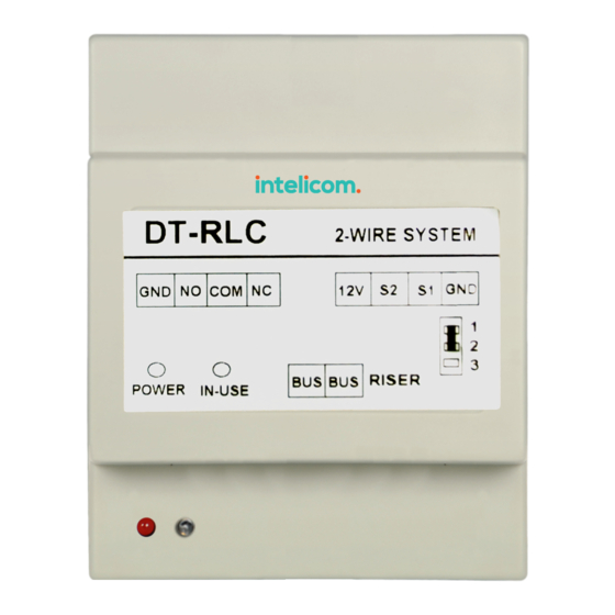
DT-RLC
User Manual
Please read this manual carefully before using the product you purchase, and
keep it well for future use.We reserve the right to modify the specification in
this manual at any time without notice.
Relay actuator
DT-RLC
2-WIRE SYSTEM
GND NO COM NC
12V S2
BUS BUS RISER
POWER
IN-USE
S1 GND
1
2
3
Advertisement

Summary of Contents for 2easy DT-RLC
- Page 1 DT-RLC Relay actuator User Manual DT-RLC 2-WIRE SYSTEM GND NO COM NC 12V S2 S1 GND BUS BUS RISER POWER IN-USE Please read this manual carefully before using the product you purchase, and keep it well for future use.We reserve the right to modify the specification in...
- Page 2 1.About DT-RLC Unit Description: The relay actuator DT-RLC is a accessory device designed for DT system to control door locks or lights. It has the features as follows: • It has two work modes: lock control mode and light control mode;...
-
Page 3: Unit Mounting
Note that the factory default is lock control mode. 1).In DIP1 = ON, DIP2 = ON, DIP3 = OFF status, exit button(S1 and GND) short- circuit, meanwhile, the DT-RLC will power-on to activate the setting mode; 2).In setting status, struck repeatedly DIP1 four times to switch work modes: A.When the IN-USE indicator flashes once, it means the system will enter the lock... - Page 4 5. Lock Control Mode In lock control mode, the DT-RLC allows to open gate door locks; Support high power- consumption lock; With configurable unlock timed output; Support exit control button. 5.1 How to set the unlock time In lock control mode: 1).
- Page 5 Applies to door station4 & lock 1 Applies to door station4 & lock 2 ON,ON,ON 5.3 Internal powered lock connection(only suitable for Power-on-to- unlock type) DT-RLC control the second lock of door station 1 Exit Button E-lock 1# Camera (Device Address:0)
- Page 6 2-3. 1 2 3 Jumper position in 1-2 DT-RLC 5.4 External Power Supply powered lock connection A. Power-on-to-unlock type: DT-RLC control the second lock of door station 1 adaptor for the lock E-lock Exit Button 1# Camera (Device Address:0)
- Page 7 Here's lock type is Exit Button E-lock Electronic lock. 1 2 3 Jumper position in 1-2 DT-RLC B.Power-off-to-unlock type: DT-RLC control the second lock of door station 1 adaptor for the lock Exit Button EM-lock 1# Camera (Device Address:0) monitor DT-RLC...
- Page 8 1 2 3 Jumper position in 2-3 DT-RLC 6. Light Control Mode In light control mode, the DT-RLC allows to control lights; With configurable light timed output; Support exit control button. 6.1 How to set the light working time In light control mode: 1).
- Page 9 Set to the fifth DT-RLC. OFF,ON,ON Set to the sixth DT-RLC. ON,ON,OFF Set to the seventh DT-RLC. ON,ON,ON Set to the eighth DT-RLC. 6.3 DT-RLC Connections for Light Control 110~250V AC Input (Device Address:0) monitor DT-RLC 2-WIRE SYSTEM COM NC...
- Page 10 7. Connecting 2 DT-RLCs In one system, you can connect a DT-RLC to control gate door lock, and connect another DT-RLC to control light. adaptor for the lock E-lock Exit Button Safety Type: power-on to open power-off to lock DT-RLC...
-
Page 11: Specification
8. Specification • Power Supply : DC24V; • Unlocking Time: 1~30s(Default 1s); • Lock Power supply: 12Vdc, 450mA(Internal Power); • Working Temperature: C~+40 • Dimension: 89(H)×71(W)×45(D)mm. The design and specifications can be changed without notice to the user. Right to interpret and copyright of this manual are preserved.
Need help?
Do you have a question about the DT-RLC and is the answer not in the manual?
Questions and answers