Table of Contents
Advertisement
Quick Links
---------------------------------------------------------------------------------------------------------------------------------------------------------
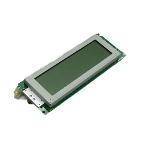
Dot matrix LCD Module Manual
1. FUNCTIONS & FEATURES
Features
一 Dot Matrix: 240×64 Dots
一 LCD Mode: STN
一 Controller IC: T6963C or Equivalent
一 Driving Method: 1/64Duty; 1/9 Bias
一 Viewing Angie: 6 O'clock direction
一 8080 serial 8-Bit MPU Interface
一 Backlight: LED
一 Operating Temperature Range: -20 to +70℃;
一 Storage Temperature Range : -30 to +80℃;
Note: Color tone is slightly changed by temperature and driving
voltage.
2. MECHANICAL SPECIFICATIONS
ITEM
Module Size
View Area
Effective Area
Dot Size
Dot Pitch
24064B
LCD MODULE USER MANUAL
SPECIFICATIONS
180.0L×65.0W×12.5H
132.0×39.0
240×64
0.49×0.49
0.53×0.53
UNIT
mm
mm
dots
mm
mm
1
Advertisement
Table of Contents

Summary of Contents for ZETTLER 24064B
- Page 1 --------------------------------------------------------------------------------------------------------------------------------------------------------- Dot matrix LCD Module Manual 24064B LCD MODULE USER MANUAL 1. FUNCTIONS & FEATURES Features 一 Dot Matrix: 240×64 Dots 一 LCD Mode: STN 一 Controller IC: T6963C or Equivalent 一 Driving Method: 1/64Duty; 1/9 Bias 一 Viewing Angie: 6 O’clock direction 一...
- Page 2 --------------------------------------------------------------------------------------------------------------------------------------------------------- 3. EXTERNAL DIMENSIONS 4. BLOCK DIAGRAM 5. POWER SUPPLY 6. PIN DESCRIPTION ITEM SYMBOL LEVEL FUNCTION — Frame Ground Power Ground +5.0V Power Supply For Logic...
- Page 3 --------------------------------------------------------------------------------------------------------------------------------------------------------- — Contrast Adjust Write Signal Read Signal /CE(CS) Chip Select Signal L:Data Write H:Command Write — No connection /RST Reset Signal 11~18 DB0~DB7 Data Bus Font selection H: 6x8 L: 8x8 — VOUT Negative Power output For LCD Driving LEDA +5.0V Power Supply For LED Backlight...
- Page 4 --------------------------------------------------------------------------------------------------------------------------------------------------------- — /CE, /RD, /WR pulse width — Data set-up time — Data hold time — Access time Output hold time MPU write timing 9. FUNCTION SPECIFICATIONS 9.1. Adjusting The LCD Display Contrast A Variable-Resistor must be connected to the LCD module for providing a reference to V0.The recommended value of the Variable-Resistor is 20K to 50K.
- Page 5 --------------------------------------------------------------------------------------------------------------------------------------------------------- 9.2. Resetting The LCD Module The LCD module should be initialized by using /RST terminal. When turning on the power supply maintain /RST terminal at low level. After the power supply stabilized, released the reset terminal.(/RST=H) Items Symbol Unit —...
- Page 6 --------------------------------------------------------------------------------------------------------------------------------------------------------- Display Control Instructions(continue)
- Page 7 --------------------------------------------------------------------------------------------------------------------------------------------------------- Note: When sending commands or data, status check must be performed. Otherwise, T6963C can’t operate normally, even after a delay time. For the details of the commands and T6963C operate please refer to T6963C datasheet. 10. DESIGN AND HANDING PRECAUTION 10.1.
- Page 8 --------------------------------------------------------------------------------------------------------------------------------------------------------- 10.11. Take care and prevent get hurt by the LCD panel edge. 10.12. Never operate the LCD module exceed the absolute maximum ratings. 10.13. Keep the signal line as short as possible to prevent noisy signal applying to LCD module.
Need help?
Do you have a question about the 24064B and is the answer not in the manual?
Questions and answers