Advertisement
Quick Links
Advertisement

Related Manuals for Luiton LT-298


Summary of Contents for Luiton LT-298
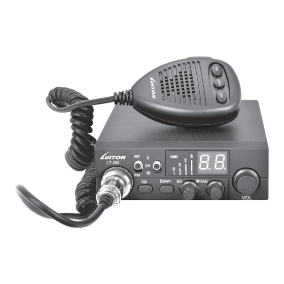
- Page 1 Luiton LT-298 SERVICE MANUAL...
- Page 2 -TECNNICAL CHARACTERITICS 1-GENERAL: -Multiconfiguration(E,d,d2,EU,EC,U,PL) -E ⇒ 40 channels AM/FM 4W (from 26,965Mhz to 27,405Mhz) -d ⇒ 80 channels FM 4W (from 26,565Mhz to 27,405Mhz) 12 channels AM 1W (from 27,005Mhz to 27,135Mhz) -d2 ⇒ 40 channels FM 4W (from 26,565Mhz to 27,405Mhz) 12 channels AM 1W (from 27,005Mhz to 27,135Mhz) -EU ⇒...
- Page 3 3-RECEPTION: -Maximum sensitivity at 20dB sinad -0,5µV(-113dBm) AM/FM -Audio frequency response -From 300Hz to 3kHz in AM/FM -Adjacent channel selectivity -Superior to 60dB -Frequency image rejection -Superior to 60dB -Intermodulation response -Superior to 54dB -Maximum audio power -Squelch sensitivity -Threshold 0,2µV(-120dBm)/Tight 1mV(-47dBm) -Current drain -500mA nominal/800mA maximum...
- Page 4 ALIGNMENT PROCEDURE LUTION LT-298 * VCO/PLL PORTION - Alignment procedure - Test points - Frequencies chart * TRANSMITTER - Alignment procedure - Test points * RECEIVER - Alignment procedure - Test points Test equipement required Frequency counter 200 Mhz HF Generator...
- Page 5 ALIGNMENT VCO/PLL 1 - Alignment procedure(13,2V;configuration“PL”) STEP CONDITION ADJUSTMENT REMARKS OF ADJUSTMENT FM(PL) Connecting a voltmeter to test TX mode TP6,to reach 2.2V±0,2V. Channel 19 FM(PL) Connecting a voltmeter to test RX mode TP6,to reach 2.2V±0,2V Channel 19 FM(PL) TX/ Connect a voltmeter to TP6,and check: RX mode Rx Channel 1=1.8V±0,2V...
- Page 6 - FREQUENCY LIST (PL) Channels Frequencies Frequencies (MHz) (MHz) 26,960 37,660 26,970 37,670 26,980 37,680 27,000 37,700 27,010 37,710 27,020 37,720 27,030 37,730 27,050 37,750 27,060 37,760 27,070 37,770 27,080 37,780 27,100 37,800 27,110 37,810 27,120 37,820 27,130 37,830 27,150 37,850 27,160 37,860...
- Page 7 - FREQUENCY LIST (CE,E,EU) Channels Frequencies Frequencies (MHz) (MHz) 26,965 37,655 26,975 37,665 26,985 37,675 27,005 37,695 27,015 37,705 27,025 37,715 27,035 37,725 27,055 37,745 27,065 37,755 27,075 37,765 27,085 37,775 27,105 37,795 27,115 37,805 27,125 37,815 27,135 37,825 27,155 37,845 27,165 37,855...
- Page 8 - FREQUENCY LIST (U) Channels CEPT Frequencies Frequencies (MHz) (MHz) 26,965 37,665 26,975 37,675 26,985 37,685 27,005 37,705 27,015 37,715 27,025 37,725 27,035 37,735 27,055 37,755 27,065 37,765 27,075 37,775 27,085 37,785 27,105 37,805 27,115 37,815 27,125 37,825 27,135 37,835 27,155 37,855 27,165...
- Page 9 - FREQUENCY LIST (U) Channels Frequencies Frequencies (MHz) (MHz) 27,60125 38,30125 27,61125 38,31125 27,62125 38,32125 27,63125 38,33125 27,64125 38,34125 27,65125 38,35125 27,66125 38,36125 27,67125 38,37125 27,68125 38,38125 27,69125 38,39125 27,70125 38,40125 27,71125 38,41125 27,72125 38,42125 27,73125 38,43125 27,74125 38,44125 27,75125 38,45125 27,76125 38,46125...
- Page 10 - FREQUENCY LIST (d) Channels Channels Frequencies Frequencies Frequencies Frequencies (MHz) (MHz) (MHz) (MHz) 26,965 37,665 26,565 37,265 26,975 37,675 26,575 37,275 26,985 37,685 26,585 37,285 27,005 37,055 26,595 37,295 27,015 37,715 26,605 37,305 27,025 37,725 26,615 37,315 27,035 37,735 26,625 37,325 27,055...
- Page 11 ALIGNMENT TRANSMITTER 1 - Alignment procedure(13,2V;configuration”PL,EU”) STEP CONDITION ADJUSTMENT REMARKS OF ADJUSTMENT VR2(LOW) AM(EU) Connect a wattmeter to jack antenna, adjust VR2 to reach 1W on Channel 20 the wattmeter. VR1(HI) FM(PL) Connect a wattmeter to jack antenna, adjust VR1 to reach 4W on Channel 20 the wattmeter.
- Page 12 ALIGNMENT RECEIVER 1 - Alignment procedure(13,2V;configuration”PL”) STEP CONDITION ADJUSTMENT REMARKS OF ADJUSTMENT T1-T2-T3 AM(PL) Channel Connect HF generator to jack antenna T4-T5 20 Middle adjusted at ( –107dBm 1KHz 60%), volume level. connect sinad meter to jack EXT speaker No squelch active and adjust coils for maximum sensitivity( ≥...
- Page 13 LUITON LT-298 COMPONENT LAYOUT...
- Page 20 LUITON LT-298 BLOCK DIAGRAM...
- Page 21 ASQ DET 1ST MIX RF ATT AF AMP AM DET AF AMP AF PWR Q13 Q12 FM DET AGC AMP RSSI RF GAIN BAND L8 L10 Q21 Q22 L11 L14 SQ VOL SQ CONT Q29 Q27 Q25 FINAL SP SW RX METU DRIVE BUFFER...
- Page 22 LUITON LT-298 SCHEMATIC DIAGRAM...
- Page 23 AUDIO_IN C126 100P C188 R189 R118 R100 333P R202 820R 100R LM7809 MMBT3904 S9018L 180P 0.6x4.5Rx20T V_RX C197 V_RX LUITON LT-298 223P C119 C208 C159 C210 R196 333P Size Number Revision 104P 470uF 103P C200 103P 200R C211 102P 1000uF/25V...
-
Page 24: Components List
LUITON LT-298 COMPONENTS LIST... - Page 25 Description / Specifications Remark amount Double plate, thickness 1.6mm HASL process size: 114 * HED-308(V 139mm 0603 0Ω 5% 1/10W RoHS R49, R154, R155, R26 0805 0Ω 5% 1/8W RoHS 0603 2.2Ω 5% 1/10W RoHS 0603 10Ω 5% 1/10W RoHS R9, R58, R80, R82, R195, R198 0603 100Ω...
- Page 26 0603 120p±10% RoHS 0603 15p±5% RoHS C130,C98, 0805 152p±10% RoHS 0603 20p±5% RoHS 0603 22p±5% RoHS C66, C97, C137 0805 220p±10% RoHS C125 0603 222p±10% RoHS C190 0603 223p±10% RoHS C27, C41, C42, C82, C88, C95, C106, C138, C142, C179, C183, 0603 272p±10% RoHS 0603 224p±10% RoHS C108, C129...
- Page 27 113 S9018L SOT23 RoHS Q2, Q4, Q8, Q9, Q7, 114 2SC1623(L6) SOT23 RoHS Q25, Q26, Q27, Q29 115 2SC2712(LY) SOT23 RoHS Q12, Q13, Q19, Q21, Q23, Q24, 116 SS8550 SOT23 RoHS Q15, Q16, Q30, Q35 117 3361D01 SOP16 RoHS 118 ICMCD2926 SSOP16 RoHS 119 NJM2902V-TE2 SSOP14 RoHS 120 NJM2904V-TE2 SSOP8 RoHS 121 MB95F354EPF-G-SNE2 SOP-24...
- Page 28 10 X12 120mm Single-ended 2P-row seat feet away from 2.0mm) away fr SL16-KY Antenna head ROHS UL2468-18AWG 270mm UL2468 194 CB308 ABS LT-298 CB308 AB 195 CB308 ABS CB308 AB CB308 SQ/RF ABS CB308 S 197 CB308 VOL ABS CB308 VO...
- Page 29 6 core aviation female plug MIC R9.7X6.8(59±2dB) ROHS 25*14*9.5mm Miandian ROHS Dust Network R25mm microphone in hand before the shell screen LT-298 Microphone in hand before the shell is not silk microphone in hand after shell painting After the hand microphone shell ABS...
Need help?
Do you have a question about the LT-298 and is the answer not in the manual?
Questions and answers