Advertisement
Quick Links
A Subsidiary of BRAY INTERNATIONAL, Inc.
DESIGN
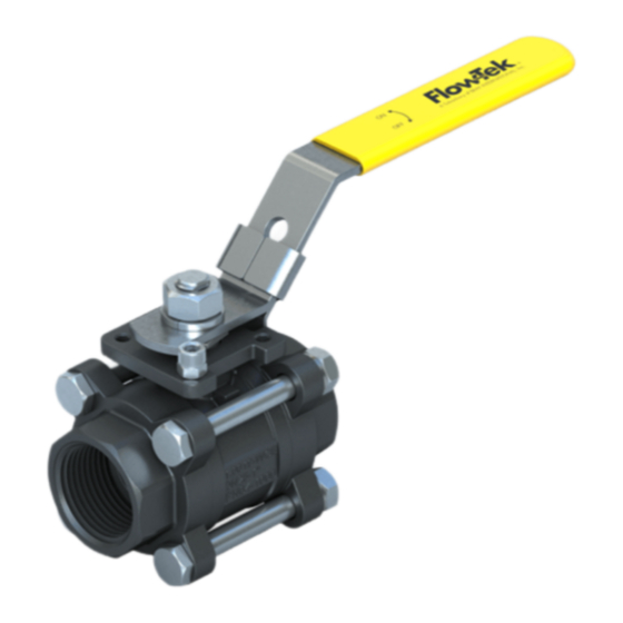
The design features three piece construction and a "free
floating" ball allowing ease of maintenance without special
tools.
The ball is not fixed, but is free to move with the line pressure.
These valves are capable of tight shut-off with flow in either
direction regardless of the position of the valve in the line.
The downstream seat, opposite the pressurized side of a closed
valve, must carry the load exerted by the line pressure on the
ball, while the upstream seat is subject to little load or wear.
For this reason, it is sometimes possible to increase useful seat
life by turning the valve end-for-end in the pipeline.
1. USE:
The valve should be inspected regularly as part of a
preventative maintenance program. Flow-Tek's recommended
pressure, temperature and corrosion limits should be followed
to ensure a long service life. During shipment, storage, and
in operation, the valve should be fully open or fully closed
("open" is preferred for shipping and storage). Do not use in
throttling service without investigating the consequences of
flow and pressure conditions to the valve.
WARNING: Before installing this equipment, confirm
that it is suitable for the intended service.
The identifications tags describe the maximum allowable
service conditions for this product.
Be sure that the installation is protected by appropriate pressure
control and safety devices to ensure that acceptable limits
are not exceeded.
2. OPERATION:
Operation of the valve is by turning the handle a 1/4 turn
(90 degrees). CW to close, CCW to open.
A. VALVE OPEN POSITlON
The handle is parallel with the pipeline.
B. VALVE IN CLOSED POSITION
The handle is perpendicular to the pipeline.
FLOW-TEK, Inc.
8323 N. Eldridge Pkwy #100
Houston, Texas 77041
®
5000/6000 SERIES BALL VALVES
INSTALLATION - MAINTENANCE MANUAL
Tel: 832.912.2300
Fax: 832.912.2301
www.flow-tek.com
Installation and Maintenance Manual
Series 5000 and 6000 Ball Valves
Date: August 2020 / Page 1 of 6
Valves with actuators should be checked for actuator -valve
alignment. Misalignment will result in high operational torque
and damage to valve stem and seals.
STEM SEAL ADJUSTMENT:
Stem seal leakage may be corrected without disassembly by
tightening the packing gland nut gradually until the leakage
stops. If the leakage continues after adjustment or the valve
operating torque becomes excessive, the seals are worn and
should be replaced.
3. GENERAL INFORMATION FOR ON-SITE
INSTALLATION:
Please read completely and understand all instructions
provided prior to beginning installation or maintenance.
The pipes must be flushed clean of dirt, burrs, and welding
residues before installing the valve, or the seats and ball
surface will be damaged.
The valve may be installed in any position on the pipeline.
Care should be taken to insure that actuator misalignment does
not occur or the valve may experience premature failure. The
actuator may require support to avoid binding the valve stem.
The pipe ends must be correctly aligned and spaced as to not
induce stresses in the valve.
As shipped from the factory, Valves may contain non-silicone
lubricant. This is for break-in and may be removed by solvent
washing, if it is undesirable in a particular application.
INSTALLATION OF THREADED END VALVES:
1. The use of a thread sealant is recommended; Use
conventional sealant, such as hemp core, Teflon, etc;
2. Do not tighten by applying torque to the opposite end
cap or other valve components. Apply a wrench only to
the hex/octagon nearest the valve end being tightened.
Tightening by using the valve body, handle or the opposite
end cap can seriously damage the valve; Use a wrench
on both the second end cap and pipe to avoid applying
torque to the body through the bolting.
© 2020 Flow-Tek, Inc.
Advertisement

Subscribe to Our Youtube Channel
Related Manuals for Bray Flow-Tek 5000 Series


Summary of Contents for Bray Flow-Tek 5000 Series
- Page 1 Installation and Maintenance Manual Series 5000 and 6000 Ball Valves ® Date: August 2020 / Page 1 of 6 A Subsidiary of BRAY INTERNATIONAL, Inc. 5000/6000 SERIES BALL VALVES INSTALLATION - MAINTENANCE MANUAL DESIGN Valves with actuators should be checked for actuator -valve alignment.
- Page 2 Series 5000 and 6000 Ball Valves ® Date: August 2020 / Page 2 of 6 A Subsidiary of BRAY INTERNATIONAL, Inc. 3. In some applications, threaded end valves may be back- body cavity. Ball valves can trap pressurized media when closed. Flush line with the valve 1/2 open to welded on site.
-
Page 3: Visual Inspection
Series 5000 and 6000 Ball Valves ® Date: August 2020 / Page 3 of 6 A Subsidiary of BRAY INTERNATIONAL, Inc. Disassembly for servicing seats and stem seals may be performed 8. Install the seats (4) and body seals into the body ends. - Page 4 Installation and Maintenance Manual Series 5000 and 6000 Ball Valves ® Date: August 2020 / Page 4 of 6 A Subsidiary of BRAY INTERNATIONAL, Inc. COMPONENTS Item Name Qty. Body End Cap Ball Seat Stem Body Seal Washer 1/4” - 2” Valves...
- Page 5 Installation and Maintenance Manual Series 5000 and 6000 Ball Valves ® Date: August 2020 / Page 5 of 6 A Subsidiary of BRAY INTERNATIONAL, Inc. 2 1/2” - 4” Valves NEED OTHER EXPLODED VIEWS © 2020 Flow-Tek, Inc. FLOW-TEK, Inc.
- Page 6 Installation and Maintenance Manual Series 5000 and 6000 Ball Valves ® Date: August 2020 / Page 6 of 6 A Subsidiary of BRAY INTERNATIONAL, Inc. 8. Short and Long Term Storage: 9. Safety Summary Short-Term Storage: 1. Read completely and understand all instructions...
Need help?
Do you have a question about the Flow-Tek 5000 Series and is the answer not in the manual?
Questions and answers