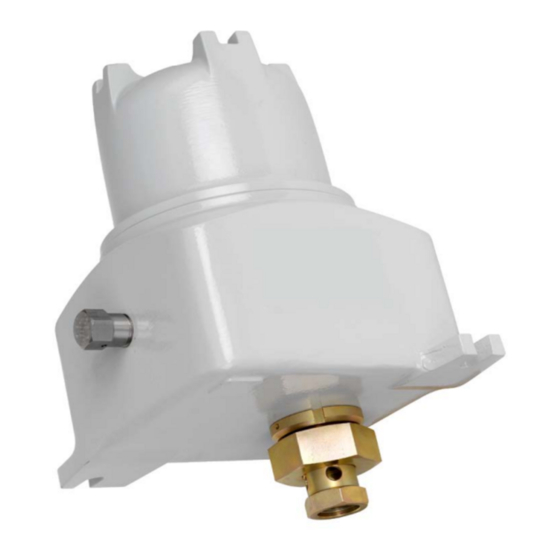
Summary of Contents for Cameron CLIF MOCK CD-20SFA
- Page 1 CLIF MOC K ™ CD-20SFA Sample Probe Controller User Manual Class I Groups C and D Hazardous Locations Manual No. 2350754-01, Rev. 02...
-
Page 2: Important Safety Information
© 2013 Cameron International Corporation (“Cameron”). All information contained in this publication is confidential and proprietary property of Cameron. Any reproduction or use of these instructions, drawings, or photographs without the express written permission of an officer of Cameron is forbidden. -
Page 3: Table Of Contents
CD-20SFA Sample Probe Controller Table of Contents Contents Important Safety Information ..........................ii Section 1—Overview ............................5 How It Works ..............................6 Hazardous Location Safety Compliance ...................... 6 Table 1.1—CD-20SFA Specifications ......................7 Section 2—Installation and Wiring........................7 Section 3—Maintenance ............................ 8 Operational Test ............................ - Page 4 Table of Contents CD-20SFA Sample Probe Controller WARRANTY - LIMITATION OF LIABILITY: Seller warrants only title to the products, software, supplies and materials and that, except as to software, the same are free from defects in workmanship and materials for a period of one (1) year from the date of delivery.
-
Page 5: Section 1-Overview
CD-20SFA Sample Probe Controller Section 1—Overview The CD-20SFA Sample Probe Controller is engineered to provide pulse input (flow proportional) control of the True-Cut C-Series sample probe. When a “start” pulse is received, the probe is rotated to capture and discharge an isokinetic sample. When installed in a horizontal line, the probe is stopped in the closed position, while on a vertical line the probe is stopped in the open position. -
Page 6: How It Works
CD-20SFA Sample Probe Controller The CD-20SFA motor control assembly (Figure 1.2) consists of a control card and power board mounted to a ring, which in turn, is mounted to the back of the CD-20SFA gear motor. All field connections are to terminal block 1TB on the control card. -
Page 7: Section 2-Installation And Wiring
CD-20SFA Sample Probe Controller Table 1.1—CD-20SFA Specifications 24 VDC 115/230 VAC Temperature -40ºC to 55ºC -40ºC to 55ºC Voltage 24VDC @2A max 115 / 230 VAC @ 1A max Pulse Input 12VDC 12VDC Transistor Output 12VDC max @ 100mA max 12VDC max @ 100mA max Current Draw (Controller) 30 mA... -
Page 8: Section 3-Maintenance
CD-20SFA Sample Probe Controller Note The input pulse contact must be closed for at least 5 msec to produce a start pulse. An electronic square wave input must have a pulse amplitude of 12VDC. A 5VDC square wave will not work. PROX ( Holdî) LED ì... -
Page 9: Basic Cd-20Sfa Check-Out
CD-20SFA Sample Probe Controller Basic CD-20SFA Check-Out 1. Disconnect the probe from the CD-20SFA. 2. Disconnect the input power from the CD-20SFA. 3. Connect a push-button switch to 1TB-5 and 1TB-6 on the control card. 4. Reconnect input power to the CD-20SFA. 5. - Page 10 CD-20SFA Sample Probe Controller • When set by a start pulse, the RUN/STOP latch U5A outputs the speed command voltage to the summing point control amplifier U2A. • Amplifier U2B provides current feedback to the summing point control amplifier U2A. •...
-
Page 11: Factory Repairs
To maintain certification, repairs must be performed by a UL-authorized Cameron facility. Attempts to modify the product at any other location will make the certification invalid. To return a product for repair, contact Cameron to request an Return to Manufacturer Authorization (RMA) form and shipping instructions. - Page 12 + 6 0 3 .5 5 6 9 .0 5 0 1 ms-kl @ c-a-m.com R U S S I A...

Need help?
Do you have a question about the CLIF MOCK CD-20SFA and is the answer not in the manual?
Questions and answers