Advertisement
PmodIA™ Reference Manual
Revised January 20, 2016
This manual applies to the PmodIA rev. A
Overview
The PmodIA is an impedance analyzer built around the Analog Devices AD5933 12-bit Impedance Converter
Network Analyzer.
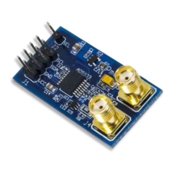
The PmodIA.
1
Functional Description
The PmodIA utilizes Analog Devices AD5933 with its on-board frequency generator and analog-to-digital converter
(ADC) to be able to excite an external unknown impedance at a known frequency. This known frequency is sent
out through one of the SMA connectors. The frequency response is captured by the other SMA connector and sent
to the ADC and a discrete Fourier transform (DFT) is performed on sampled data, storing the real and imaginary
parts of the solution in the on-chip data registers. The magnitude of the unknown impedance as well as the
relative phase of the impedance at each point in the generated frequency sweep can be calculated from these two
data words.
DOC#: 502-246
Other product and company names mentioned may be trademarks of their respective owners.
Features include:
Impedance analyzer with 12-bit impedance
converter
Measure impedance values ranging from 100Ω
to 10 MΩ.
Programmable frequency sweep
Programmable gain amplifier
Optional external clock generation
Small PCB size for flexible designs 1.6 in × 0.8
in (4.1 cm × 2.0 cm)
2×4-pin connector with I²C interface
Follows Digilent Interface Specification
Library and example code available in
center
Copyright Digilent, Inc. All rights reserved.
1300 Henley Court
Pullman, WA 99163
509.334.6306
www.digilentinc.com
resource
Page 1 of 5
Advertisement
Table of Contents

Related Manuals for Digilent PmodIA

Summary of Contents for Digilent PmodIA
- Page 1 PmodIA™ Reference Manual Revised January 20, 2016 This manual applies to the PmodIA rev. A Overview The PmodIA is an impedance analyzer built around the Analog Devices AD5933 12-bit Impedance Converter Network Analyzer. Features include: Impedance analyzer with 12-bit impedance converter ...
-
Page 2: Clock Source
Clock Source The PmodIA has an internal oscillator that generates a 16.776 MHz clock to run the device. You can use an external clock by loading IC4 on the PmodIA and setting bit 3 in the control register (register address 0x80 and 0x81). - Page 3 PmodIA™ Reference Manual Setting up a Frequency Sweep The electrical impedance, ��, of a circuit can vary over a range of frequencies. The PmodIA allows you to easily set up a frequency sweep to find the impedance characteristics of a circuit.
-
Page 4: Temperature Readings
∠�� = ������ �������� The PmodIA does not perform any calculations. After each DFT, the master device must read the values in the Real and Imaginary registers. In order to calculate the true impedance, you must take into account the gain. You can find an example gain factor calculation in the AD9533 data sheet. - Page 5 PmodIA™ Reference Manual Copyright Digilent, Inc. All rights reserved. Page 5 of 5 Other product and company names mentioned may be trademarks of their respective owners.
Need help?
Do you have a question about the PmodIA and is the answer not in the manual?
Questions and answers