Advertisement
Quick Links
A clock is a precision mechanical instrument containing many
slowly moving parts. There are over a hundred points of contact
where friction works to bring it to a stop.
Take your time assembling this kit, and pay attention to the
details. Great pains have been taken to craft these instructions
to ensure your success. If there are any steps that seem unclear,
please let us know.
Before you begin, check that there are no missing or damaged
pieces in the kit. A parts list is provided to help identify each
piece.
Finally, read through all the instructions before you begin. This
will help you understand how each piece fits into the finished
clock.
WARNING!
CHOKING HAZARD - CONTAINS
SMALL PARTS. NOT RECOMMENDED
FOR CHILDREN UNDER 3 YEARS
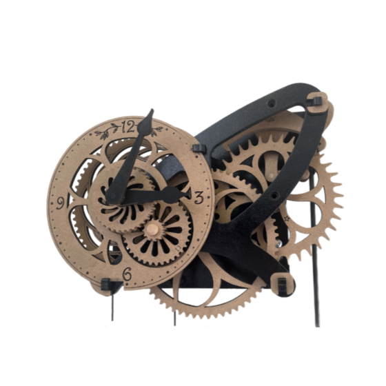
WALL CLOCK KIT
SEBRINGVILLE
Made in Canada by
ABONG, Inc
5-775 Woodlawn Road W
Guelph, ON N1K 1Y7
DAMAGED OR MISSING PARTS?
email: service@abong.com
Advertisement

Summary of Contents for ABONG SEBRINGVILLE 3157826
- Page 1 Finally, read through all the instructions before you begin. This will help you understand how each piece fits into the finished clock. Made in Canada by ABONG, Inc 5-775 Woodlawn Road W Guelph, ON N1K 1Y7 WARNING! DAMAGED OR MISSING PARTS? CHOKING HAZARD - CONTAINS SMALL PARTS.
- Page 2 Six laser cut sheets are supplied with the kit. • There are two thicker boards, one large and one small with parts labels beginning with ‘A’ • There is one thinner board with parts labels beginning with ‘B’ • There is one thinner board with parts labels beginning with ‘C’ •...
- Page 3 The kit also contains a number of other components needed to complete the clock.
- Page 4 The tools needed to assemble this kit are: • Razor saw (42 teeth per inch) • Scissors...
- Page 5 The supplies needed to complete the kit are: • Two or three sheets of good quality, fine grit (220) sandpaper • Cyanoacrylate gel glue (also called “CA”, crazy, or super glue). • Wood glue (also called carpenter’s or PVA glue) •...
- Page 6 Using 220 grit sandpaper, sand both faces of each part to remove blemishes and residue left by the laser cutting process. For large pieces, use a sanding block, which can be as simple as a piece of scrap wood with sandpaper wrapped around it.
- Page 7 For small pieces, lay the sandpaper flat and move the part against it. Take care not to remove any laser etched marks. Taking a little extra care and patience to prepare each piece will make a huge impact on the appearance of the completed kit.
- Page 8 To sand holes and smaller openings, tear a small strip of sandpaper and tightly roll it into a cone shape small enough to fit. Work the sandpaper into the opening, twirling it as it is moved in and out.
- Page 9 To sand gear teeth, fold a strip of sandpaper twice, and sand each tooth across the thickness of the material. Work around the rim of the gear first working on one side of each tooth, then flip the gear over, and sand the other side.
- Page 10 The dark edge left by the laser cutting process is caused by natural resins in the material. It does not bond well with glue. The instructions will include diagrams indicating which edges need to be sanded. Lightly sand the highlighted edges to expose the material beneath.
- Page 11 Before applying glue, always test the fit of the parts. Carefully sand any joints that bind so the parts fit together smoothly. Sand the end of alignment pins, rods, and tubes to remove any rough edges. It is critical that the parts are fully inserted, and all edges are in contact to ensure correct operation of the finished clock.
- Page 12 Wood glue (also known as carpenter’s glue or PVA) is used to “tack” parts together. It takes longer to dry and allows the parts to be adjusted before the glue sets and hardens. The symbol below indicates wood glue is required in a step...
- Page 13 CA glue (also known as cyanoacrylate glue, crazy glue or super glue) is used to permanently bond parts together. It is available as a liquid or gel. The gel type is preferable for this application as it stays where applied. This glue will “sieze”...
- Page 14 Carbon fiber is tough and can be challenging to cut. Always use a sharp blade and follow these steps to get the best results. Secure the piece to be cut. Some options are: • a miterbox • a vice • a block of scrap wood...
- Page 15 Wrap the area to be cut with masking tape. Measure and mark the masking tape where the part Lightly draw the saw over the part to score it on the will be cut. marked line. This will help prevent the blade from wandering.
- Page 16 If you wish to apply a finish to the kit, craft paints are a simple and effective method. Carefully apply the paint to completed components before final assembly. Avoid getting finish onto any edge or surface that will be glued or or contact other parts while the clock is running..
- Page 17 Use the guide (AL) as a reference to cut four ‘LONG’ sections of carbon fiber tube. Ensure the ends are cut flat, and the length is accurate. Use a sharp razor saw, jig saw, or dremel tool. Wear a mask and safety glasses.
- Page 18 Use the guide (AL) as a reference to cut three ‘SHORT’ sections from the remaining carbon fiber tube. Use a sharp razor saw, jig saw, or dremel tool. Wear a mask and safety glasses. There will be a length of tube left over. Set it aside as a spare.
- Page 19 Use the guide (AL) as a reference to cut eight ‘SHORT’ sections from the small dowel. These are alignment pins. Use a sharp razor saw, jig saw, or dremel tool. Wear a mask and safety glasses. There will be a length of dowel left over. Set it aside as a spare.
- Page 20 Use CA glue to attach three long spacers (DE) to the Insert a ‘LONG’ section of tube into the guide (AL). end plate. Do not glue! Slip on an end plate (DK) . Do not glue! Do not get glue on the tube! Use CA glue to attach an end plate (DK) to the long spacers (DE).
- Page 21 Repeat the previous six steps to create a second long spacer assembly.
- Page 22 Use CA glue to attach three short spacers (DJ) to the Insert a ‘LONG’ section of tube into the guide. end plate (DK). Do not glue! Slip on an end plate (DK). Do not glue! Do not get glue on the tube! Use CA glue to attach an end plate (DK) to the short spacers (DJ).
- Page 23 Sand the edges marked in red of the three frame spacers (AB), the pendulum anchor (AC), and the baseplate (AA). Use 220 grit sandpaper. A secure glue joint is critical for this load-bearing component!
- Page 24 Place the baseplate (AA) on a flat surface marked side up. Use CA glue to attach the three frame spacers (AB) and the pendulum anchor (AC) to the base plate. Note the orientation of the notches.
- Page 25 Use CA glue to attach the pendulum anchor (BA) and pendulum cord guide (BB) to the base plate (AA). Note the orientation of the notch.
- Page 26 Test fit the front plate (AD) to the frame. Do not glue! Test fit the two retainer clips (DH) and the clock face (BC) to the frame. The clock face slides into the notches in two frame spacers as shown. Do not glue! Remove the clock face (BC), retainer clips (DH), and front plate (AD).
- Page 27 Place a “SHORT” section of tube into the tool (AL) and Apply CA glue to the joint between the spacer ring Press a pulley flange (DI) onto the spacer ring (DF), slip on a spacer ring (DF). Do not glue! (DF) and the tube.
- Page 28 Sand the edges marked in red of the two counterweight faces (DC), the two sides (DB), the bottom (DA) and the top (CH). Use 220 grit sandpaper. A secure glue joint is critical for this load-bearing component!
- Page 29 Use CA glue to attach the counterweight bottom Use CA glue to attach the two counterweight sides Slip the counterweight pulley into the counterweight (DA) to the marked side of a counterweight face (DC). (DB) to the counterweight face (DC) and the bottom back.
- Page 30 Fill the counterweight with BBs (not supplied). Use CA glue to attach the counterweight top (CH) Use CA glue to attach the decorative plate (BD) to the front counterweight face (DC).
- Page 31 Use CA glue to attach the guide ring (CJ) and backing Use CA glue to fit the metal weight inside the guide Use CA glue to attach the trim plate (BK) to the plate (BL) to the marked side of the pendulum bob ring (AK).
- Page 32 Sand the indicated edges of the the pendulum crown (AG) and the crutch (BI). Use 220 grit sandpaper.
- Page 33 Join the two long carbon fiber rods using CA glue and a ‘SHORT’ section of tube. This forms the pendulum rod. Place the pendulum crown (AG) marked side down on a flat surface. Use CA glue to attach one end of the pendulum rod to the pendulum crown (AG). Slip the pendulum bob onto the other end of the pendulum rod.
- Page 34 Slip a small axle pin through the unmarked side of the crutch (BI). Glue the axle pin Trim the small axle pin to the unmarked side of the pendulum crown (AG). This to the marked side of the pendulum crown (AG). Note the crutch should pivot easily completes the pendulum.
- Page 35 Use 220 grit sandpaper to sand each tooth of the second wheel gear (BM) and a pinion (AE) to remove residue left by the laser cutting process. Use 220 grit sandpaper as needed to provide a sliding fit between the holes in both the second wheel gear (BM) and the pinion (AE) and the tube.
- Page 36 Place a ‘LONG’ section of tube into the hole the baseplate (AA) marked with a triangle. Do not glue!
- Page 37 Slip a long spacer assembly (ring side down) onto the tube. Do not glue! Slip a pinion (AE) onto the long spacer assembly. Do not glue! Slip a spacer ring (DF) onto the pinion (AE). Apply a bead of wood glue to the joint Press the second wheel gear (BM) marked side up onto the spacer ring.
- Page 38 Assemble the faceplate (AD) to the assembled base using the clock face (BC) and retaining clips (DH).
- Page 39 Before the wood glue sets, slowly rotate the second wheel assembly while examining it edge-on. The space between the second wheel gear (BM) and the faceplate (AD) should be consistent to prevent wobbling. Continuing rotating the assembly and adjusting as neccessary while the glue dries.
- Page 40 Remove the clock face (BC), retaining clips (DH) and faceplate (AD) from the Press a spacer ring (DF) onto the second wheel gear (BM). assembled base. Apply CA glue to the joint between the second wheel gear (BM) and the tube.
- Page 41 Remove the second wheel from the assembled base, and the long spacer assembly Press the pinion (AE) onto the spacer ring. and pinion (AE) from the tube. Apply CA clue to the joint between the pinion (AE) and the tube on the unmarked Apply CA clue to the joint between the spacer ring (DF) and the tube on the side of the second wheel gear (BM).
- Page 42 Use 220 grit sandpaper to sand each tooth of the escape wheel gear (CA) and a pinion (AE) to remove residue left by the laser cutting process. Use 220 grit sandpaper as needed to provide a sliding fit between the holes in both the escape wheel gear (CA) and the pinion (AE) and the carbon fiber tube.
- Page 43 Place a ‘LONG’ section of tube into the hole the baseplate (AA) marked with a Slip a long spacer assembly (ring side down) onto the tube. Do not glue! triangle. Do not glue! Slip a spacer ring (DF) onto the long spacer assembly. Apply a bead of wood glue to Press the escape wheel gear (CA) marked side up onto the spacer ring.
- Page 44 Assemble the faceplate (AD) to the assembled base using the clock face (BC) and retaining clips (DH).
- Page 45 Before the wood glue sets, slowly rotate the escape wheel assembly while examining it edge-on. The space between the escape wheel gear (CA) and the faceplate (AD) should be consistent to prevent wobbling. Continuing rotating the assembly and adjusting as neccessary while the glue dries.
- Page 46 Remove the clock face (BC), retaining clips (DH) and faceplate (AD) from the Press a pinion (AE) onto the escape wheel gear (CA). assembled base. Apply CA glue to the joint between the pinion (AE) and the tube. Apply CA glue to the joint between the escape wheel gear (CA) and the tube. Press a spacer ring (DF) onto the pinion (AE).
- Page 47 Press the long spacer assembly onto the pinion (AE) This completes the escape wheel.
- Page 48 Use 220 grit sandpaper to sand the working faces of the pallets (AF). Work carefully, and do not alter the shape of the part Use 220 grit sandpaper as needed to provide a sliding fit between the holes in both the pallets (AF) and the pallet backing plate (BJ) and the tube.
- Page 49 Place a ‘LONG’ section of tube into the hole the baseplate (AA) marked with a Slip the pallet backing plate (BJ) marked side up onto the tube. Do not glue! triangle. Do not glue! Press two alignment pins into the holes in the pallet backing plate (BJ). Use CA glue to attach the pallets (AF) to the pallet backing plate (BJ) and alignment Remove the pallets from the tube, then trim and sand the alignment pins flush with pins...
- Page 50 Place the short spacer assembly ring side down onto the tube. Press the pallet assembly marked side up onto the short spacer assembly. Apply CA glue to the joint between the short spacer assembly and the tube. Apply CA glue to the joint between the pallets (AF) and the tube. Press a spacer ring (DF) onto the pallets (AF).
- Page 51 Press a third spacer ring (DF) onto second spacer ring (DF). Remove the pallets from the assembled base. This completes the pallets.
- Page 52 Use 220 grit sandpaper to sand each tooth of the winder wheel gear (BH) to remove residue left by the laser cutting process. Use 220 grit sandpaper as needed to provide a sliding fit between the hole in the winder wheel gear (BH) and the tube. Use 220 grit sandpaper on the pawl spacers (DD) to remove residue left by the laser cutting process from the edges highlighted in red.
- Page 53 Place a ‘LONG’ section of tube into the hole the baseplate (AA) marked with a Slip a spool thumbwheel (CD) onto the tube, Do not glue! triangle. Do not glue! Press two alignment pins into the spool thumbwheel (CD) Use CA glue to attach a spool core (CE) to the spool thumbwheel (CD) and alignment Use CA glue to attach a second spool core (CE) to the previous spool core (CE) and pins.
- Page 54 Use CA glue to attach the second spool thumbwheel (CD) to the spool core (CE) and Use CA glue to attach the ratchet spacer (CC) marked side up onto the spool alignment pins. Do not allow glue to come into contact with the tube! thumbwheel (CD).
- Page 55 Place the winder wheel gear (BH) face down on a flat, smooth surface. Use CA glue to attach four pawl spacers (DD) to the winder wheel gear (BH). Ensure they are fully inserted and correctly oriented. Use CA glue to attach four alignment pins into the winder wheel gear (BH) Slip the pawls (DG) onto the alignment pins.
- Page 56 Trim the alignment pins flush with the surface of the pawl retainer (CG). Ensure the pawls are retracted and assemble the two halves of the winder wheel. Do not glue! The retainer plate (CG) should be flush against a spool thumbwheel (CD) with the ratchet fully inserted into the pawls.
- Page 57 100. Slip the assembled winder wheel onto the tube. Ensure the ratchet is still fully Press a spacer ring (DF) onto the winder wheel gear. engaged. Apply wood glue to the joint between the winder wheel gear (BH) and the tube.
- Page 58 101. Assemble the faceplate (AD) to the assembled base using the clock face (BC) and retaining clips (DH).
- Page 59 102. Before the wood glue sets, slowly rotate the winder wheel assembly while examining it edge-on. The space between the winder wheel gear (BH) and the faceplate (AD) should be consistent to prevent wobbling. Continuing rotating the assembly and adjusting as neccessary while the glue dries.
- Page 60 103. 104. Remove the clock face (BC), retaining clips (DH) and faceplate (AD) from the Press a second spacer ring (DF) onto the previous spacer ring (DF). assembled base. Apply CA glue to the joint between the second spacer ring (DF) and the tube. Apply CA glue to the joint between the spacer ring (DF) and the tube.
- Page 61 107. 108. Remove the winder wheel from the assembled base, and the spacer ring Press a spacer ring onto the tube until it ‘just’ contacts the spool from the tube. Ensure the ratchet is still fully engaged. thumbwheel (CD). Do not allow glue to come into contact with the spool! Apply a thin bead of CA glue to the tube near the spool thumbwheel (CD).
- Page 62 109. When held upright, the spool should rotate independantly of winder wheel gear and tube in one direction, while the entire assembly rotates together in the other.
- Page 63 110. Use 220 grit sandpaper to sand each tooth of the idler gear (CI), idler pinion (AJ), hour gear (AI), and hour pinion (AH) to remove residue left by the laser cutting process. Use 220 grit sandpaper as needed on the holes in the idler gear (CI), idler pinion (AJ), hour gear (AI), hour pinion (AH), hour hand spacer (BE) and the hour hand (BH) to ensure they spin freely on their axles.
- Page 64 111. 112. Place the faceplate (AD) marked side up on a clean flat surface. Center the idler spacer ring (CB) over the small hole in the baseplate (AD). Do not glue! 113. 114. Center the idler gear (CI) over the idler spacer ring (CB). Do not glue! Place an axle pin though the pivot hole of the idler pinion (AJ) and press the assembly through the hole in the idler gear (CI), idler spacer ring (CB) an into the Apply a ring of CA glue around the pivot hole in the idler gear (CI)
- Page 65 115. 116. Remove the axle pin and idler assembly from the baseplate. Place the axle pin though idler assembly and idler spacer ring (CB) 117. 118. Apply CA glue around and in the small hole in the faceplate (AD) Press the axle pin into the hole in the faceplate, leaving a gap roughly the thickness of a piece of paper between the head of the axle pin and the idler.
- Page 66 119. 120. Place a ‘SHORT’ section of tube into the hole the guide (AL) . Slip the hour gear (AI) onto the tube (do not glue). 121. 122. Use CA glue to attach the hour hand spacer (BE) to the hour gear (AI). Do not allow Use CA glue to attach the hour hand (BF) marked side down onto the hour hand glue to contact the tube! spacer (BE).
- Page 67 123. 124. Remove the hour hand assembly and tube from the guide (AL) Slip a spacer ring (DF) onto the end of the ‘SHORT’ section of tube. It must be even with the end of the tube. Apply a bead of CA glue to the joint between the spacer ring (DF) and the tube.
- Page 68 127. 128. Slip a spacer ring onto the hour hand assembly. Leave a gap roughly the thickness of Press the minute hand (BG) marked side down onto the spacer ring (DF). a piece of paper to allow the hour hand assembly to spin freely. Apply CA glue to the joint between the spacer ring (DF) and the tube.
- Page 69 131. Use 220 grit sandpaper to remove any residue from the axle holes in the base plate (AA). The tube should spin freely in each of the marked holes.
- Page 70 132. Use 220 grit sandpaper to remove any residue from the axle holes in the faceplate (AD). The tube should spin freely in each of the marked holes.
- Page 71 133. Place the winder wheel in the hole marked with a club.
- Page 72 134. Slip the dial face (BC) under the idler gear.
- Page 73 135. Attach the faceplate (AD) to the assembled base using the dial face (BC) and two retainer clips (DH).
- Page 74 136. 137. View the winder wheel from the edge on. There should be a small gap (< 1mm) If the top retaining ring is touching the frame, remove the winder wheel and the top between the top retaining ring and the frame. If there is, skip the next three steps. retainer ring (DF).
- Page 75 140. Spin the wheel. It should rotate freely and gently coast to a stop. If it does not, sand the axle holes in the base plate (AA) and faceplate (AD) again with 220 grit sandpaper. Repeat as needed.
- Page 76 141. Remove the winder wheel and install the second wheel in the hole marked with a triangle. Ensure it rotates freely and gently coasts to a stop, sanding the axle holes and repeating the test as needed.
- Page 77 142. Remove the second wheel and install the escape wheel in the hole marked with a star. Ensure it rotates freely and gently coasts to a stop, sanding the axle holes and repeating the test as needed.
- Page 78 143. Install the winder wheel and second wheel. Spin the winder wheel clockwise and ensure both wheels spin with minimal friction and coast to a stop. If they ‘catch’ and stop suddenly, mark the teeth on the larger gear where it meshes with the pinion.
- Page 79 144. Remove the winder wheel and second wheel, and install the escape wheel and second wheel Spin the second wheel counterclockwise and ensure both wheels spin with minimal friction and coast to a stop. If they ‘catch’ and stop suddenly, mark the teeth on the larger gear where it meshes with the pinion.
- Page 80 145. Install all three wheels Spin the winder wheel clockwise and ensure all wheels spin with minimal friction and coast to a stop. If they ‘catch’ and stop suddenly, mark the teeth on the larger gear where it meshes with the pinion. Ensure all residue has been removed, and lightly sand the root of that tooth and the adjacent ones.
- Page 81 146. Apply CA glue to the hole in the pallet backing plate (BJ)
- Page 82 147. Align the hole in the crutch (BI) and the hole in the pallet backing plate (BJ).
- Page 83 148. Connect the pendulum to the pallets by pressing an axle pin through the back of the crutch (BI) and through the pallet backing plate. There should be a gap roughly the thickness of a sheet of paper between the head of the axle pin and the crutch (BI) The crutch must be able to pivot freely.
- Page 84 149. Trim and sand the axle pin flush with the surface of the pallet backing plate (BJ).
- Page 85 150. Tie a figure-of-eight knot in one end of the counterweight cord. Thread the other end through the hole in the spool thumbwheel (CD) from the back face inward. Pull the cord through untill the knot is secured against the outside face of the spool thumbwheel.
- Page 86 151. Thread the other end of the counterweight cord through the counterweight cord guide (BB) as shown. Tie a figure-of-eight knot on the free end of the cord.
- Page 87 152. Install the pallets in the hole marked with a crescent. The knife edge on the pendulum crown (AG) will rest in the groove etched into the top of the pendulum anchor (AC).
- Page 88 153. Install the winder wheel into the hole marked with a club, and the escape wheel into the hole marked with a star.
- Page 89 154. Install the second wheel into the hole marked with a triangle.
- Page 90 155. Install the faceplate (AD) using the dial face (BC) and retainer clips (DH).
- Page 91 156. 157. Hang the clock on the wall Step 1 Hang the clock on the wall Step 2 158. 159. Hang the clock on the wall Step 3 Hang the clock on the wall Step 4...
- Page 92 160. Thread the free end of the counterweight cord through the counterweight pulley as shown.
- Page 93 161. Slide the knotted end of the counterweight cord into the counterweight anchor as shown,...
- Page 94 162. While supporting the counterweight, turn the spool thumbwheels counterclockwise to wind the clock.
- Page 95 163. Press the dial train rod into the center of the winder wheel carbon fiber tube. Ensure the minute gear pinion is engaged with the idler gear.
- Page 96 164. Place the knife edge of the pendulum crown (AG) into the groove etched in the counterweight anchor.
Need help?
Do you have a question about the SEBRINGVILLE 3157826 and is the answer not in the manual?
Questions and answers