
Summary of Contents for Silverpak 17D
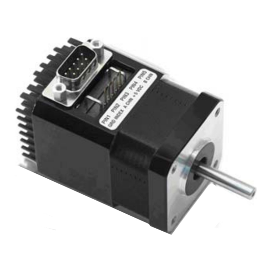
- Page 1 17D / 17DE INTEGRATED STEP MOTOR AND DRIVER With Encoder Option USER MANUAL Version 1.05...
- Page 2 Thank you for purchasing the Silverpak 17D or 17DE - Integrated Motor and R208 Driver. This product is warranted to be free of manufacturing defects for one year from the date of purchase. Our technical support group is glad to work with you in answering your questions. If you cannot find the solution to your particular application, or, if for any reason you need additional technical assistance.
- Page 3 Silverpak 17D/DE User Manual Product: Silverpak 17D and Silverpak 17DE Version: 1.05 Date: 7/22/2010 Version History Version Date Description of Changes 1.00 1.01 04/10/2006 Edited Encoder information 1.02 02/02/2007 Standardization of user manuals 1.03 6/7/2007 Added min. order qty for R208-05;...
-
Page 4: Table Of Contents
IMING 4. MECHANICAL SPECIFICATIONS 7 IMENSIONS 5. CONNECTORS 9 6. GETTING STARTED 10 ALTERNATIVE STEP RESOLUTION CONNECTION 11 7. CONFIGURING AND CONTROLLING THE 17D 11 SIGNAL CONTROL SPECIFICATIONS 11 INTERNAL SCHEMATIC 12 ESISTOR ALUES FOR THE UPPLY 8. TROUBLESHOOTING 13 Page 4 Version 1.05... -
Page 5: Features
Channel B Table 1: Encoder Pinouts *Optional Index Channel Default Settings Default Settings Table 2 The 17D is set to these default settings Step Resolution 8x Microstep when Pins 2, 3, 4, and 5 are left open. Direction of rotation Counterclockwise Holding Current 23% of motor’s... -
Page 6: Electrical Specifications
Steps per Revolution (1.8° Motor) 200, 400, 800, 1600 *NOTE: The Silverpak 17D/DE by default use 23% of the run current as it’s hold current. If you require more holding torque, the other option is to use 100% of the run current as your holding current, which must be special ordered. -
Page 7: Power Supply Requirements 6 Driver 6 Motor Specifications 6 Logic Input Timing
Standard length is 0.94”. Customized length is available. Motor Shaft Diameter Standard shaft diameter is 0.1968”. Customized diameter length is also available. Overall Body Length Motor body length is available in various lengths DO-4118S (2.69”) DO-4118M (2.92”) DO-4118L (3.24”) Page 7 Version 1.05 Silverpak 17D 7/22/2010... -
Page 8: Dimensions
Dimensions Figure 2: Dimensions Diagram Page 8 Version 1.05 Silverpak 17D 7/22/2010... -
Page 9: Connectors
5. CONNECTORS A DB-9 female connector cable receives power and provides the control connections for the 17D Unit. Active signals are optically isolated. An open-collector drive is required to provide pulses for Step, levels for Direction and Disable/Enable. PIN #... -
Page 10: Getting Started
6. GETTING STARTED In order to properly connect your new 17D Unit, first take a look at Figure 4, below. Here’s a list of the parts needed to make the motor run: • +12 to 24 Volt Power Supply •... -
Page 11: Alternative Step Resolution Connection
Please refer to the Table 3 for Step Resolution Settings. PLEASE NOTE: The microstepping resolution should not be changed on the fly, loss of step may occur. 7. CONFIGURING AND CONTROLLING THE 17D SIGNAL CONTROL SPECIFICATIONS Step Resolution Table 4: Step Resolution Settings... -
Page 12: Internal Schematic
INTERNAL SCHEMATIC The 17D has 3 optically isolated logic inputs. These inputs are isolated to minimize or eliminate electrical noise coupled onto the drive control signals. Each input is internally pulled-up to the level of the optocoupler supply and may be connected to sinking outputs on a controller or a PLC. -
Page 13: Troubleshooting
Changing the microstepping "on the fly" might ruin the driver. It is recommended to disable the motor from running (either turn power off, or use the disable pin), then change the step resolution. Page 13 Version 1.05 Silverpak 17D 7/22/2010...
Need help?
Do you have a question about the 17D and is the answer not in the manual?
Questions and answers