Advertisement
Overview

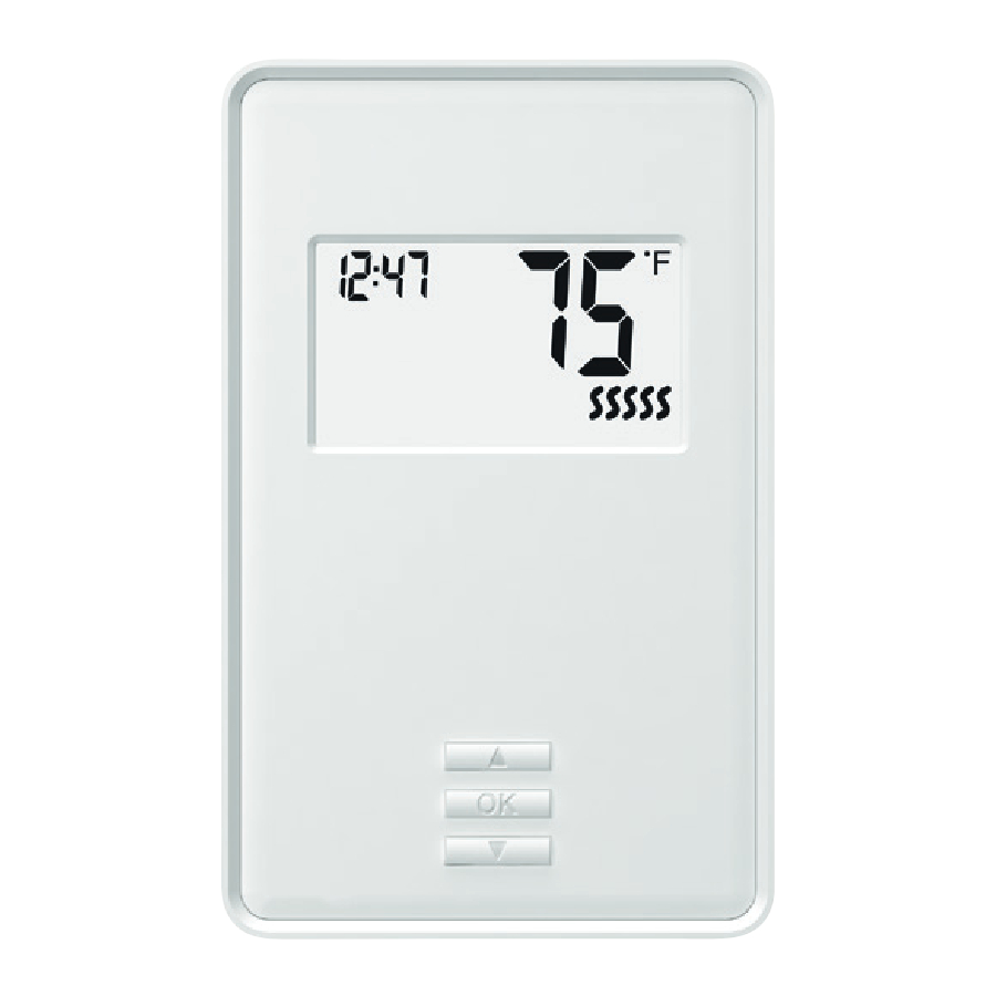
The marked values are default values

- GFCI Test Button
- On/Off/GFCI Reset Button
Press to turn system ON
Hold to turn system OFF
Press to reset the GFCI - The sensor cable shall be separated from power cables.
The floor sensor must be centered in between the heating cable.
Installation

Loosen the screw at the bottom and remove the faceplate.
Do not attempt to remove the screw completely.

Turn power source OFF at breaker panel. Connect power supply wires to line side and heating cable wiring to load side of power base.
AWG between 12 - 20.
Note! Do not detach the screws from the terminal.
When fastening the screws use a torque between 0.8 - 1.2 Nm / 0.6 - 0.9 lbf-ft.
The floor sensor cable must be routed to the junction box 5 separate from power wires and the heating cable cold lead. Ensure that the insulation on the electrical wiring and the floor sensor inside the junction box are not damaged.

Thread the floor sensor cable through the hole in the power base. Push the electrical wires to the back of the electrical box.
Install the power base into the electrical box.

Secure the power base to the wall.
Scan the QR-code for additional information

Make the sensor connections.

The Floor sensor has no polarity. Connect it to terminals C and D.
Expansion unit connects to terminals A and B*
*Refer to instructions included with expansion unit.
Checking the GFCI
It is important that the GFCI is checked for correct installation and function upon installation and monthly thereafter.
To check the GFCI:
Press the "TEST" button.
The test is successful if the red LED on the right of the thermostat flashes once every two seconds and "GROUND FAULT" appears on the display. If this does not occur, check the installation.
Press the "Standby/Reset" button to reset the GFCI.
The red LED will stop flashing and the display returns to its normal appearance.
If the test fails, repeat the test. If it continues to fail, ask an electrician to check the installation.
If, during normal operation, the GFCI trips without the "TEST" button being pressed, there could be a ground fault! To check whether it is a ground fault or nuisance tripping, press "Standby/Reset". If this causes the red LED to stop flashing and stay off, it was nuisance tripping and the system is operating correctly. If this does not occur, there is a ground fault! In case of a ground fault, it is important to have the installation checked by a qualified electrician according to local and national regulations.
The red LED on the right of the thermostat can indicate four different GFCI states:
- LED off – NORMAL state.
- LED flashing slowly (once every two seconds) – TRIGGERED state. Try pressing the "Standby/Reset" button to reset the GFCI.
- LED flashing quickly (five flashes per second) – ERROR state. Try switching the power off and then back on again. If the thermostat re-enters the ERROR state, either the wiring is wrong (a GN exists) or the unit is defective and must be replaced.
- LED lit constantly – Internal microprocessor malfunction or abnormal fault in hardware! Try switching the thermostat off and then back on again. If the LED is still constantly lit, the GFCIis defective and the thermostat must be replaced.
Note: The LED lights up briefly without flashing during every power-up.
BASIC OPERATION
Increasing/Decreasing the Temperature
By default, the thermostat displays the CURRENT temperature. Press the Up/Down buttons ONCE to activate the backlight. Press the Up/Down buttons again to adjust the TARGET temperature between 41 to 104°F (5 to 40°C). The screen will display the TARGET temperature for ten seconds.
Setting the Time
- Press the Center button TWICE to access the Menu.
- Using the Up/Down buttons, go to 12/24 and press the Center button.
- Select the time format (12-hour clock or 24-hour clock) and press the Center button.
- Using the Up/Down buttons, go to TIME and press the Center button.
- Set the hour and press the Center button.
- Set the minutes and press the Center button.
- Using the Up/Down buttons, go to EXIT and press the Center button.
Changing the Temperature Unit
- Press the Center button TWICE to access the Menu.
- Using the Up/Down buttons, go to C/F and press the Center button.
- Select the temperature unit (Celsius or Fahrenheit) and press the Center button.
- Using the Up/Down buttons, go to EXIT and press the Center button.
Changing the Temperature Control Setting
- Press the Center button TWICE to access the Menu.
- Using the Up/Down buttons, go to FLOOR/ROOM and press the Center button.
- Select the temperature control setting and press the Center button.
- Using the Up/Down buttons, go to EXIT and press the Center button.
| Temperature Control Setting | Description |
| Floor (Default) | The floor sensor controls the heating. Floor protection is active. Limits as in Floor/Room. |
| Room | The built-in sensor controls the heating. Floor protection is NOT active. This setting is useful if the temperature sensor in the floor is damaged or none is installed. |
| Floor/Room | The built-in sensor controls the heating and the floor sensor limits the floor temperature to 104°F/40°C for Tile or 82°F/28°C for Laminate. |
Changing the Floor Type
(not selectable if the Temperature Control setting is set to ROOM – refer to 'Changing Temperature Control Setting' section). Tile is the default floor type.
- Press the Center button TWICE to access the Menu.
- Using the Up/Down buttons, go to TILE/LAMINATE and press the Center button.
- TILE - the floor temperature will be limited to 104°F/40°C
- LAMINATE - the floor temperature will be limited to 82°F/28°C.
- Select the floor type and press the Center button.
- Using the Up/Down buttons, go to EXIT and press the Center button.
Monitoring Usage
- Press the Center button TWICE to access the Menu.
- Using the Up/Down buttons, go to HISTORY and press the Center button.
- The display will show the number of HOURS (denoted by the 'h' on the right side of the screen) the floor heating system has been heating over the past 7 days. When done, press the Center button.
- Using the Up/Down buttons, go to EXIT and press the Center button.
Troubleshooting
E02 - This error message indicates a missing or damaged floor sensor.
Flashing digits indicate that the measured floor temperature is higher than the limit temperature.
Heating is switched off.
Contact your installer to verify the floor sensor and connections.
Classification
The product is a Class II device (reinforced insulation) and must be connected to the following leads:
Phase L1 (L) 120/208/240 V
Neutral/2nd phase L2 (N)
Max. load 15 A (resistive load) The thermostat is intended to be used with underfloor heating.
The terminals are suitable for field wiring cables of 12 to 20 AWG.
Technical data
Supply - (208 Vac included) 120/240 Vac
Load - max. 15 A (resistive load)
Power - 1800 W at 120 Vac
3120 W at 208 Vac
3600 W at 240 Vac
GFCI (UTN4) - Class A (5 mA trip level)
Floor sensor - NTC 10K Ω @ 25°C
Construction of Control - Electronic room thermostat for regulating electrical underfloor heating.
Method of Mounting Control - Independently mounted control for flush mounting
Type of Action - Type 2.B.
Rated Impulse Voltage - 2500 V
Control Pollution Degree - 2
USA - Design Patent No. - D768092
Canada No. - 161353
UL Listed for the US and Canada
According to the following standards:
Thermostat: UL 60730-, UL 60730-2-9
CSA E60730-1, CSA E60730-2-9
UL file number: E157297
UTN4 / GFCI: UL 943 fourth ed.
CSA C22.2 No. 144.1-06

Documents / Resources
References
Download manual
Here you can download full pdf version of manual, it may contain additional safety instructions, warranty information, FCC rules, etc.
Download ARDEX FLEXBONE HEAT Non-Programmable Thermostat Quick Start Guide
Advertisement
Need help?
Do you have a question about the FLEXBONE HEAT Non-Programmable Thermostat and is the answer not in the manual?
Questions and answers