Advertisement
Quick Links
Advertisement

Summary of Contents for RBtec IRONCLAD
- Page 1 IRONCLAD Installation Manual Scan QR Code before Installation! 1 / 28...
- Page 2 Field Equipment Installation Guide The purpose of this guide is to provide field installation instructions for the IRONCLAD sensor system. PLEASE READ THE ENTIRE MANUAL BEFORE ATTEMPTING TO INSTALL THE SYSTEM This handbook includes instructions for: To Receive an extended Warranty of 3 years on Installation of the IRONCLAD sensor cable.
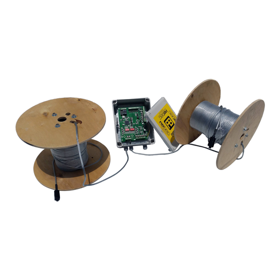
- Page 3 Required Tools For Installation Wire Cutter Flathead Voltmeter Screwdriver multimeter (Small) Wire Stripper Stainless Steel Ties (Sold Separately) 3 / 28...
- Page 4 MCTR MCTR Optimal Layout: • The diagram shown above shows how the IRONCLAD system should appear when installed correctly. • Please note the positioning of the sensor cable approximately halfway up the fence and running parallel to the ground.
- Page 5 IRONCLAD’s ability to properly filter out false signals. • IRONCLAD functions best when installed on a fence which is in good condition. Ideally, the fence should be fully intact, straight, under tension, and free of obstructions. Signs should be securely fastened.
-
Page 6: Sensor Cable Installation
Sensor Cable Installation • The sensor cable must be attached to the internal (protected) side of the fence. • Ideally, the cable should be attached in the middle of the fence and run roughly parallel to the ground. 6 / 28... - Page 7 Sensor Cable Installation On Fence • Attach the cable to the fence within the groove formed by the chain link low point (see above). • The low point creates a “channel/line” that allows the cable to sit in and have greater contact with the fence material.
- Page 8 While rotating the • Although we strongly recommend the use of tool with the other IRONCLAD ties due to the extended durability of hand pull the metal versus plastic, installation can also be done with loose side of the any outdoor UV plastic tie wraps/zip ties.
- Page 9 Sensor Cable Installation Around Poles • Create a drop loop around the poles. This allows the cable to move freely with the fence without catching on the pole. Ideal spacing is 2-3 fingerbreadths (2.5 - 4 inches) between the cable and the pole on a taught fence.
- Page 10 The IRONCLAD Sensor Wire Stripping Process Pass the screwdriver Split the GND braid to Strip the clear wire. The clear wire is the Pull the clear wire out. between the clear wire either side. sensing wire. and braid. Attention! 1. Do not use any other method of stripping other than wire strippers. (do not use lighter to burn the coating as it will harm the detection capability of the wire) 2.
- Page 11 End Of Line Termination Kit - MCTR 1M (1000k) Ohm Case Cover Cover Push Resistor Screws Terminals Holding 11 /...
- Page 12 End Of Line Termination Kit - MCTR Assembly Sequence Step 1 Step 3 Insert the cable into Connect the sensor cable to the junction box as shown. the push terminals. Step 2 Connect the resistor into the push terminals. 12 /...
- Page 13 Attention! 1. When stripping only use the proper tool, verify ALL wire strands stay intact. 2. Verify there are no shorts between the sensing wire and GND wire when connecting to the end of the line resistor. Step 4 Press the terminal onto the holding pin until it is firmly secured.
- Page 14 End Of Line Termination Unit – MCTR Cable Input Mount the MCTR with the cable input facing the ground. The end of line termination unit (MCTR) needs to be mounted at the very end of each zone. A zone won’t be able to function without one and will stay in alarm. 14 /...
- Page 15 LPU-400 Processor Parts Overview Configuration Board + Tamper CPU Board for LPU- LPU 400 Main Board LPU 400 Full Assembly Power Management Interface Board for LPU-400 Board for LPU-400 15 /...
- Page 16 Power outage Alarm Indication LPU-402 Wiring (-) DC GND – Sensor Center Ground Wire Wire Zone 1 (+) DC Zone 2 12-24 GND – Ground Wire Zone 1 Sensor Center Wire Zone 2 16 /...
- Page 17 Interface Board Inputs Overview DISARM Zone 1 & 2 Armed Chassis Ground Wire Connect the chassis wire to a Zone 1 Armed Zone true Ground. The purpose of the 2 Disarmed chassis is to protect the board against surges and lightnings Zone 1 &...
- Page 18 Alarm Output Terminals Overview Power Outage (Power Cut / Drop) Alarm Relay Output Alarm Dry Contact Relay Alarm Outputs Each Input has a dedicated output. Zone 1 will trigger Relay 1 (RLY1) LPU 400 Full Assembly By Default, the outputs are Normally Closed (NC) but can be changed to Normally Open (NO) In the LPU Calibration software if...
- Page 19 IMPORTANT! LPU-400 – Indicator The red LED has to be at number 1 Lights Overview SOLID with the fence is not touched. If there’s any flicker or it’s on any other LED other then number 1 then Power Outage there is “noise” on the sensor cable (Power Cut/Drop) that would cause false alarms.
- Page 20 Sensitivity Level Adjustment Instructions “Enter” Key Setup Sensitivity Setting Sensitivity LEDS Mode (1) Jumper Sensitivity Adjustment Exit Set-Up Low Sensitivity (UP/DOWN) (2) Mode (4) Navigator Between Navigator Zones (3) High Sensitivity Between Zones If Both Sets of LEDs are off press Reset board after “ENTER”...
-
Page 21: Swing Gate Protection
Swing Gate Protection MCTXT IRONCLAD sensor cable IRONCLAD sensor cable MCTXT MCTXT Non-sensitive cable RG6 Direct Burial under the gate in waterproof conduit 21 /... -
Page 22: Troubleshooting
It’s recommended to do a system test monthly to quarterly basis in order to verify proper operation of the system. To Receive an extended Warranty of 3 years on the Processor and Cable please Scan the QR code or go to Warranty.rbtec.com 22 /... - Page 23 This document has been written and produced by RBtec to provide the reader with as much technical and general information as possible regarding Rbtec, its products, and its services. Copying any of its contents without prior permission from RBtec is strictly prohibited.
Need help?
Do you have a question about the IRONCLAD and is the answer not in the manual?
Questions and answers