Advertisement
Quick Links
INSTALLATION INSTRUCTIONS AND HOLE-CUTTING TEMPLATE
Please read all instructions before commencing installation.
IMPORTANT
This integrated bathroom heat-fan-light unit must be installed
by a registered electrician and its installation and connection to
the power supply must comply with all current Australian and
New Zealand electrical and building regulations including
AS/NZS3000, or latest edition thereof.
The power supply cable must be suitably rated by a registered
electrician to satisfy the total load on that circuit.
FOR YOUR SAFETY
•
Use this heat-fan-light unit only as described in this manual. Any other use not recommended by the manufacturer may cause fire, electric shock,
or injury to persons. If you have questions, contact the manufacturer or local agent.
•
To prevent electrical shock, please ensure that power is DISCONNECTED before installing.
•
All wiring must be carried out by a licensed electrician in accordance with all national wiring codes.
•
When cutting into the ceiling, do not damage electrical wiring and other hidden utilities.
•
The heat-fan-light unit must be properly earthed.
•
This appliance is not intended for use by persons (including children) with reduced physical, sensory or mental capabilities, or lack of experience and knowledge,
unless they have been given supervision or instruction concerning use of the appliance by a person responsible for their safety.
•
Children should be supervised to ensure that they do not play with the unit.
•
The surface is extremely hot when in use. Allow surface to cool sufficiently before touching or replacement.
•
Exhaust fans may adversely affect the safe operation of burning gas or other fuels (including those in other rooms) due to back flow of combustion gases.
These gases can potentially result in carbon monoxide poisoning. After installation of an exhaust fan such as a partition fan or a duct fan the operation of
flued gas appliances should be tested by a competent person to ensure that back flow of combustion gases does not occur.
•
Any alterations or additions to building wiring must be completed by a licensed electrician or person authorised by legislation to work on the fixed wiring of
any electrical installation.
INTRODUCTION AND CONSIDERATIONS
•
Read these instructions carefully before installing & using the product.
•
Always operate this product from a power source of the same voltage, frequency and rating as indicated on rating label.
•
This product is designed for installation in flat ceilings only. Don't mount on a sloping ceiling or a vertical wall.
•
Locate and install the product in accordance with the requirements of AS/NZS 3000 and local building codes.
Do not install in a location where there is a possibility of water splashing into the heater.
READ AND SAVE THESE INSTRUCTIONS!
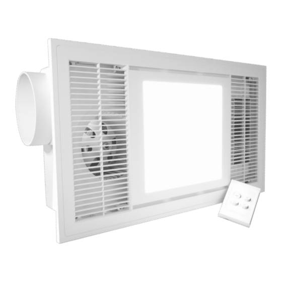
MADRID Fan Heater, Light and Exhaust
MODEL: MAD31HLX
VENTILATION REQUIREMENTS
For the exhaust fan to work efficiently, replacement air of a volume equivalent to what is being extracted must be able to enter the room.
Generally, air would be drawn under the door (20mm undercut), or through a slightly open room. If the room is airtight, the fan will operate
poorly. Air flow path should ideally pass over the steam source.
Before commencing any cutting, check in the ceiling space that there are no obstructions such as ceiling joists and that there is sufficient
height clearance for the housing. Check that the electrical wiring can be routed from the wall switches to the mounting location.
The appliance shall, under no circumstances, be covered with insulating, or similar, material.
CLEARANCE REQUIREMENTS
•
This unit must be mounted at least 250mm away from vertical walls.
•
Additionally a minimum of 50mm clearance is ris required between any part of the Madrid, and Joists, walls,
insulation and/or overhead building material.
.
Front View
Madrid 3 in 1
≥200mm
Ceiling Joist
Ceiling
≥415mm
≥250mm
INSTALLATION
1
This unit must be mounted at least 2.1 meters above the floor and at least 250mm away from vertical walls.
2
Ensure area behind the installation location is clear of all cables, pipes, joists or hidden utilities.
3
Use the template provided to mark and cut a hole in the ceiling (Refer specifications for hole size) ensure sufficient space for the clamping arms to operate.
Ensure the gap between the clamping arm and lip of the body is slightly larger than the thickness of the ceiling. Adjust accordingly.
4
Remove rear terminal cover and connect wires as per wiring diagram below. Refit terminal cover.
Note: Connect ducting (if required) after the unit is installed in the ceiling.
5
Gently insert the unit into the cut out hole ensuring to move the side clamping arms inwards so that the body can pass through the hole without damaging the plasterboard.
Rotate all 6 clamping arms out using the levers then gently tighten the 6 screws to clamp and secure the unit.
6
Connect the LED panel power connector.
7
Attach the fascia to the body aligning the "HEATER" marking in the inside of the fascia with the "HEATER" marking on the HFL body and tighten screws avoid overtightening
DO NOT use an electric drill or impact driver.
8
Attach ducting to extract the air to the soffit or outer wall using 3m long flexible ducting, duct clamp and vent outlet grille provided.
Fix and tighten duct clamp firmly to hold the flexible duct to the unit and the outer wall vent. To maximise airflow, , cut the duct to size, as required, ensuring it is in a fully expanded
state with minimal bends or corners.
Door
Airflow
Window
WARNING
RISK OF OVERHEATING OR FIRE
IF THE CLEARANCE DISTANCES
ARE COMPROMISED.
Typical Installation example.
Duct
Madrid 3 in 1
Ceiling Joist
Ceiling
≥685mm
≥250mm
Please use this card as a cutting template 590mm x 320mm
Advertisement

Related Manuals for Ventair MADRID MAD31HLX


Summary of Contents for Ventair MADRID MAD31HLX
- Page 1 INSTALLATION INSTRUCTIONS AND HOLE-CUTTING TEMPLATE Door MADRID Fan Heater, Light and Exhaust VENTILATION REQUIREMENTS MODEL: MAD31HLX For the exhaust fan to work efficiently, replacement air of a volume equivalent to what is being extracted must be able to enter the room. Airflow Generally, air would be drawn under the door (20mm undercut), or through a slightly open room.
- Page 2 Instructions are subject to change without notice. Ventair Pty Ltd 4 Capital Place, Carrum Downs, VIC, 3201, Australia 330m/hr e: info@ventair.com.au I w: www.ventair.com.au AIRFLOW (L/sec) READ AND SAVE THESE INSTRUCTIONS! Please use this card as a cutting template 590mm x 320mm...