
Subscribe to Our Youtube Channel
Related Manuals for NeoDen IN12

Summary of Contents for NeoDen IN12
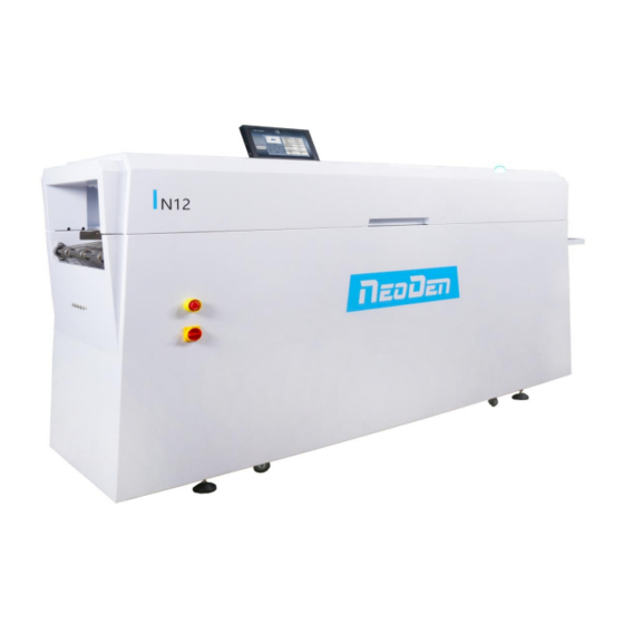
- Page 1 Zhejiang NeoDen Technology Co., Ltd. User Manual V1.1 Reflow Oven NeoDen IN12 Power saving with built-in smoke filtering system With smart temperature curve testing system Easy operation...
-
Page 2: Table Of Contents
Content 1. Brief Introduction ....................2-3 2.Specification .....................4-4 3.Main Parts......................5-6 3.1 Reflow Oven Main Body................ 5-5 3.2 Operating Panel..................5-5 3.3 Cover and heating zone................6-6 4.Installation Instruction..................7-11 4.1 Power Supply Connection...............7-7 4.2 Installation Attentions................7-7 4.3 Status of Indicators..................8-8 4.4 Operation instructions................ -
Page 3: Brief Introduction
Please read the user manual carefully before operating this machine. 1. Introduction IN12 is a newly designed and manufactured reflow oven by NeoDen Tech. It has 12 temperature zones, unique heating module design, intelligent control system, built-in soldering smoke filtering system, which makes it intelligent, innovative, compact and high-performance. - Page 4 19. The optimized soldering fume filter systems tested by the dedicated airflow simulation software can filter harmful gases as well as ensuring IN12 can keep room temperature, reducing heat loss and reducing working power consumption.
-
Page 5: Specification
2. Specification Model NeoDen IN12 Heating Zone Quantity Upper6 / Down6 Cooling Fan Upper4 Controller VGUS Microcomputer Transmission Mesh Chain Drive Heating Type Nichrome Wire & Aluminum Alloy Heating Conveyor Speed 50~600 mm/min Temperature Range Room temperature~300℃ Temperature Accuracy 1℃... -
Page 6: Main Parts
3. Main Parts 3.1 Reflow Oven Main Body 3.2 Operating Panel... -
Page 7: Cover And Heating Zone
3.3 Cover and Heating Zone 3.31 Heating Zone... -
Page 8: Installation Instruction
, it’s better to directly use 4mm 2.5mm , then it can only connect with one set of IN12 Reflow oven, other equipment Will not be allowed to connect together. ♦ The machine should be set in standard SMT workshop, stay away from flammable and explosive if couldn’t meet previous requirements. -
Page 9: Status Of Indicators
4.3 Status of Indicators There’s tri-color light on top of the cover, it is used to indicate whether all zones’ temperature have reached the well-set temperature. When all temperature reach to well-set temperature, indicator light up green; While in the heating-up status, indicator will flash as yellow;... - Page 10 Text box File List ♦Save and use of soldering formula ♦Save method: Click ‘SAVE AS’ on the main control page or click the file list page on the left to enter the file management page. Select the location you want to save (the file list box will turn green when selected).
- Page 11 ♦File generation Wizard (Note: due to the great difference in complexity of each product, the temperature parameters generated are only used as reference. In order to achieve the best solder effect, it is necessary to measure the temperature curve and improve the parameters after comparing with the temperature curve provided by the solder paste manufacturer.) Step 1: select the type of solder paste to solder the product.
- Page 12 ♦Temperature curve Connect the Temperature sensor to the SENSOR CONNECTOR, attach the sensor to PCB, and then click "start" button in the curve setting interface after PCB is put into the oven to get the temperature curve, click "stop" to pause the generation of temperature curve, and click "clear"...
-
Page 13: Temperature Wave Setting Principle
5.Temperature wave setting principle 5.10 what is the heating unit temperature? the real-time temperature of the heating plate. 5.11 what is oven temperature? the air temperature between the chain surface and the heating plate. 5.12 what is PCB surface temperature? the temperature of component soldering feet when PCB is soldered. - Page 14 The following equipment and Auxiliary tools are required before starting the wave procedure High precision temperature profiler ( with IN12), thermocouple (with IN12), tools for attaching thermocouple to PCB (mainly high temperature tape) and solder paste parameter table.
- Page 15 melting point of alloy and the desired maximum temperature of reflow. Before you start, you must have a basic understanding of the ideal temperature wave. Theoretically, the ideal wave consists of four parts or sections, the first three regions are heated and the last one is cooled. The more the temperature zone of the oven, the more accurate and close the profile of the temperature wave can be achieved.
- Page 16 always lower than the melting point of the alloy, and the peak temperature is always at the melting point. The typical peak temperature range is 205 ~ 230℃. if the temperature is set too high in this area, the temperature rise slope will exceed 2 ~ 5℃...
- Page 17 example, the automatic trigger of 38°C (100°F) allows the thermometer to start working as soon as the PCB is put on the conveyor chain and into the furnace, so that the thermocouple will not be triggered by mistake when it is handled by the human.
- Page 18 Figure 4:Set too high/low temperature of active zone Figure 5:Soldering too much/little...
-
Page 19: Details About Temperature Area Setting
Figure 6:Cooling too much/little When the final temperature profile is as close as possible to the desired profile, tke record or store of the parameters for later use. Although this process is slow and laborious at first, it can eventually gain proficiency experience, resulting in high- efficiency production of high-quality PCBs. -
Page 20: Temperature Measurement Method
different areas, the setting temperature of PCBs with few pads is correspondingly lower. There is also a certain connection with the amount of boards released per unit time. However, in normal production, the soldering machine has its own adjustment system for general PCB board changes. The soldering machine can be used for normal production at the recommended temperature during training, unless the heat absorption of the PCB changes significantly.,then need do adjust accordingly. -
Page 21: Precautions
heating speed Decrease transfer speed and temperature Reduce top heat and increase bottom zone Excessive fines Top layer temperature out of limit temperature Due to dry too fast Decrease transfer chain speed and temperature Tin balls Solder pasting is unqualified or PCB re- Use PCB after cleaning and drying paste Flux coking... -
Page 22: Machine Maintenance
other suitable carriers to place the soldered PCB. *It is not recommended to open the incubator when it is not necessary. If it must be opened, the incubator must be supported by a support rod before the next work can be carried out. - Page 23 The filter assembly needs to be replaced regularly, and the service life of the filter assembly is 8 months (depending on the service frequency). The following is the replacement tutorial. Prepare the filter assembly and a cross screwdriver before replacement; Left concave Right concave Left wind shield...
- Page 24 ♦ Regularly add high temperature lubricating oil to transfer chain bearings.
Need help?
Do you have a question about the IN12 and is the answer not in the manual?
Questions and answers