Table of Contents
Advertisement
Quick Links
Advertisement
Table of Contents

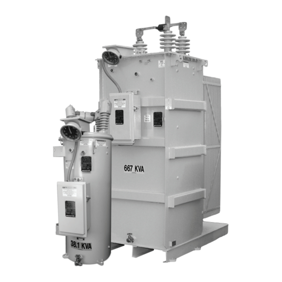
Summary of Contents for Howard Industries SVR-1
- Page 1 Switch-Pad™ SVR-1 Step Voltage Regulator Instructions Installation, Operation, and Maintenance of SVR-1 Step Voltage Regulators Howard Industries, Inc. ISO-9001 Certified Document No. 2.4.114 Copyright © 2017 Howard Industries, Inc. Revision: 05 Issued: October, 2017...
- Page 2 Features presented herein may not be present in all equipment designs. Standard and optional features are subject to change without notice. Howard Industries makes no representation or warranty with respect to and assumes no responsibility for the completeness, accuracy, sufficiency, or usefulness of these instructions.
-
Page 3: Table Of Contents
Figure 6: Connection diagram, two SVR-1 regulators in an open delta three-phase system .......... 9 Figure 7: Connection diagram, three SVR-1 regulators wye connected in a three-phase four-wire system ....9 Figure 8: Connection diagram, three SVR-1 regulators delta connected in a three-phase three-wire system ......9 Figure 9: HI-AMP™... -
Page 4: Receiving Inspection, Storage, And Handling
Discrepancies should also be brought to the attention of the Howard Industries Regulator Division. HANDLING The regulator can be moved using the lifting lugs on the sides of the tank and a suitably rated lifting sling. -
Page 5: Installation
SVR-1 Step Voltage Regulator INSTALLATION INTRODUCTION An SVR-1 regulator can regulate the voltage on a single- phase circuit or one phase of a delta- or wye-connected three-phase circuit as described below and as illustrated in the connection diagrams on page 9. Do not connect three regulators in a wye configuration on a three-phase, three-wire circuit. -
Page 6: Installation Location
Then connect the “S” bushing to the source and the “L” bushing to the load. Standard bushing terminals for the SVR-1 are provided as indicated in the following table and are suitable for connection MOUNTING to copper or aluminum conductor. Clamp-type con-... -
Page 7: Control Connections
“S” and “L” bushings using the supplied mounting provi- sions. The top lead of each arrester should be connected SVR-1 regulators may be operated at less than the rated to the adjacent bushing terminal. Arrester grounding is voltage as indicated on the nameplate. When operated at achieved through the arrester mounting brackets. -
Page 8: Figure 4: Svr-1 Step Voltage Regulator
(mounted on control enclosure) Laser-engraved nameplate (tank-mounted) Tank grounding provi- sions (2) Drain valve and oil sampling device Bolt-down provisions (4) FIGURE 4: SVR-1 step voltage regulator. Copyright © 2017 Howard Industries, Inc. Document No. 2.4.114 Revision: 05 Issued: October, 2017... -
Page 9: Figure 5: Connection Diagram, One Svr-1 Regulator In A Single-Phase System
FIGURE 6: Two SVR-1 regulators in an open delta three- phase system. Bypass Switch Bypass Switch Bypass Switch Disconnects Shunt Arrester Series Arrester FIGURE 7: Three SVR-1 regulators wye connected in a three-phase four-wire system. Bypass Switch Bypass Switch Bypass Switch Disconnects Shunt Arrester Series Arrester FIGURE 8: Three SVR-1 regulators delta connected in a three-phase three-wire system. -
Page 10: Placing A Regulator In Service
(Figure 9). The HI-AMP™ feature allows the SVR-1 regulator to be operated above rated load by decreasing the range of operation in 1.25 percent increments. Load current may be increased up to 160 percent of rated current (maximum of 668 Amps) when the regulator is operated at ±... -
Page 11: Checking For Proper Operation
6. Set the MOTOR CONTROL AUTO/MANUAL switch to indicator illuminates. the “AUTO” position, After a time delay, the regulator will automatically return to an IN-BAND condition. The control panel IN-BAND indicator will illuminate. Document No. 2.4.114 Copyright © 2017 Howard Industries, Inc. Revision: 05 Issued: October, 2017... -
Page 12: Removing A Regulator From Service
Open the source “S” disconnect switch*. on pages 10 and 11. 8. Open the load “L” disconnect switch*. Copyright © 2017 Howard Industries, Inc. Document No. 2.4.114 Revision: 05 Issued: October, 2017... -
Page 13: Maintenance
SVR-1 Step Voltage Regulator MAINTENANCE GENERAL INSTRUCTIONS OPERATIONAL CHECKS SVR-1 step voltage regulators are designed for long Periodic operational checks should be performed to verify life and trouble-free operation. Periodic inspection and proper operation of the control unit, the tap changer maintenance will prolong life and minimize the likelihood mechanism, and the HI-AMP™... -
Page 14: Insulation Fluid
“MS” – Motor source tank. Be careful to avoid overhead lines. “G” – Ground • Operate pressure relief valve to vent regulator “CO” – Current transformer negative (–) Copyright © 2017 Howard Industries, Inc. Document No. 2.4.114 Revision: 05 Issued: October, 2017... -
Page 15: Vacuum Oil Fill Process
Cooling fans (when present) have sealed bearings and do not require maintenance. 3. Connect the vacuum pump suction line to the pressure-vacuum fitting near the top of the tank. Document No. 2.4.114 Copyright © 2017 Howard Industries, Inc. Revision: 05 Issued: October, 2017... -
Page 16: Additional Maintenance Instructions
Repair Parts Repair parts can be ordered from the Howard Industries Transformer Division. A description of the part and the regulator serial number will be required to ensure that the correct part has been ordered. -
Page 17: Figure 12: External Parts View
Switch-Pad™ SVR-1 Step Voltage Regulator PARTS LIST FIGURE 12: External Parts View - refer to Table 1 on the following page for parts description. Document No. 2.4.114 Copyright © 2017 Howard Industries, Inc. Revision: 05 Issued: October, 2017... -
Page 18: External Parts List
156* Controller Terminal Strip (male connector, located inside control enclosure) 157* Controller Terminal Strip (female connector, located inside control enclosure) *Not shown in reference Figure 12 Copyright © 2017 Howard Industries, Inc. Document No. 2.4.114 Revision: 05 Issued: October, 2017... - Page 19 Switch-Pad™ SVR-1 Step Voltage Regulator NOTES Document No. 2.4.114 Copyright © 2017 Howard Industries, Inc. Revision: 05 Issued: October, 2017...
- Page 20 SVR-1 Step Voltage Regulator Document 2.4.114 SVR-1 Step Voltage Regulator Installation, Operation, and Maintenance Instructions Document No. 2.4.114, Revision 5, October 2017 Copyright © 2017 Howard Industries, Inc. Laurel, Mississippi Telephone: 601-425-3151 Fax: 601-649-8090 Web howardtransformers.com Document No. 2.4.114 Copyright © 2017 Howard Industries, Inc.
Need help?
Do you have a question about the SVR-1 and is the answer not in the manual?
Questions and answers