
Summary of Contents for ELECTOR MCCAB
- Page 1 Operating Instructions Elektor Arduino NANO ® Training Board MCCAB Rev. 3.3 Elektor...
-
Page 2: Table Of Contents
Board or do not use it in accordance with its intended purpose, you alone are responsible for compliance with the applicable rules. Therefore, only use the MCCAB Training Board and all components on it as described in these operating instructions. You may only pass on the MCCAB Training Board together with this operating manual. -
Page 3: Recycling
Under no circumstances may negative voltages or voltages greater than +5 V be connected to the MCCAB Training Board. The only exceptions are the inputs VX1 and VX2, here the input voltages may be in the range of +8 V to +12 V (see section 4.2). -
Page 4: Handling And Environmental Conditions
If the MCCAB Training Board shows signs of damage (e.g., due to mechanical or electrical stress), it must not be used for safety reasons. The MCCAB Training Board may only be used in a clean and dry environment at temperatures up to +40 °C. -
Page 5: Intended Use
/ or wrong operation the user is solely responsible! Liability claims against us are understandably excluded in these cases. Any use other than that specified is not permitted! The MCCAB Training Board must not be modified or converted, as this could damage it or endanger the user (short circuit, risk of overheating and fire, risk of electric shock). -
Page 6: The Mccab Training Board And Its Components
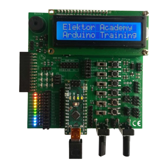
The user creates his exercise programs for the MCCAB Training Board on his PC in the Arduino IDE, a development environment with an integrated C/C++ compiler, which he can download free of charge from the website https://www.arduino.cc/en/main/software... - Page 7 Figure 1: The MCCAB Training Board, Rev. 3.3 The operating and display elements on the MCCAB Training Board: (1) 11 × LED (status indication for the in- (10) Potentiometer P2 puts/outputs D2 ... D12) (11) Pin header JP4 for selecting the sig-...
-
Page 8: The Arduino ® Nano Microcontroller Module
An Arduino ® NANO or a microcontroller module compatible with it is plugged into the MCCAB Training Board (see arrow (5) in Figure 1 as well as Figure 2 and M1 in Figure 4). This module is equipped with the AVR microcontroller ATmega328P, which controls the peripheral compo- nents on the training board. - Page 9 By means of connectors – so-called Dupont Cables (see Figure 3) – the inputs/outputs of the microcontroller (also called GPIOs = General Purpose Inputs/Outputs) led out at SV5 and SV6 can be connected to operating elements (buttons, switches, ...) on the MCCAB Training Board or to external parts.
- Page 10 (pin 2 and pin 1 of the module M1 in Figure 4) are assigned with the signals RxD and TxD of the microcontroller’s UART and are used for the serial connection between the MCCAB Training Board and the USB port of the PC. only available to the user to a limited extent...
-
Page 11: The Power Supply Of The Mccab Training Board
4.2 The power supply of the MCCAB Training Board The MCCAB Training Board works with a nominal operating DC voltage of Vcc = +5 V, which is usually supplied to it via the mini-USB socket of the Arduino ®... - Page 12 The power supply via the USB cable is switched off in this case. The +3.3 V auxiliary voltage is generated on the MCCAB Training Board by a linear voltage regulator from the +5 V operating voltage Vcc of the microcontroller module and can supply...
-
Page 13: The Usb Connection Between The Mccab Training Board And The Pc
The programs that the user develops in the Arduino IDE (development environment) on his PC are loaded into the ATmega328P microcontroller on the MCCAB Training Board via a USB cable. For this purpose, the microcontroller module on the MCCAB Training Board (arrow (5) in Figure 1) must be connected to a USB port of the user's PC via a mini-USB cable. -
Page 14: The Potentiometers P1 And P2
If one of the GPIOs D2 ... D12 is used as input, it may be necessary to deactivate the LED assigned to it by removing the jumper in order to avoid a load of the input signal by the operating current of the LED (approx. 2 ... 3 mA). The status of the GPIO D13 is indicated by its own LED L directly on the microcontroller module (see Figure 1 and Figure 2). -
Page 15: The Switches S1
4.6 The switches S1 ... S6 and the buttons K1 ... K6 The MCCAB Training Board provides the user with six pushbuttons and six-slide switches for his exercises (arrows (20) and (19) in Figure 1). Figure 7 shows their wiring. -
Page 16: The Piezo Buzzer Buzzer1
Its basic circuitry is shown in Figure 9. Buzzer1 can be connected to the GPIO D9 of the microcontroller on the MCCAB Training Board via a jumper on the position "Buzzer" of pin header JP6 (arrow (29) in Figure 1) (see Figure 9, Figure 4 and arrow (2) in Figure 1). -
Page 17: The 3 × 3 Led Matrix
1 m as a function of the signal frequency. Due to physical properties and natural resonances, certain frequencies are reproduced louder and others softer. The corresponding diagram of the piezo buzzer on the MCCAB Training Board shows a similar curve. Figure 10: Typical frequency response of a piezo buzzer (Image: Sonitron) - Page 18 The three-row connections 1, 2 and 3 are routed to the pin header JP1 (arrow (28) in Figure 1). They can be connected to the microcontroller’s pins D3 ... D5 by means of jumpers. Alter- natively, the pins 1, 2 or 3 on header JP1 can be connected via Dupont cables to any output D2 ...
-
Page 19: The Lc-Display (Lcd)
Figure 12: The connections of the LC display Contrast setting The purchaser of the MCCAB Training Board must adjust the contrast of the LC display during the first start-up! To do this, a text is output to the LCD and the... -
Page 20: The Driver Outputs Sv1 And Sv7 For Higher Output Currents And Voltages
ATmega328P. Connector A4 on pin header SV6 (arrow (7) in Figure 1) functions as data line SDA (Serial DAta) and A5 as clock line SCL (Serial CLock). The LC display on the MCCAB Training Board normally has the I C address 0x27. -
Page 21: The Sv2 Socket Connector For Linking External Modules
Even complete application models, such as training modules for control engineering or traffic light control, which require many GPIOs for their control, can be connected to the SV2 socket connector of the MCCAB Training Board and controlled by its microcontroller. -
Page 22: The Pin Headers For The Connection Of Spi Modules
The pin headers SV11 (arrow (13) in Figure 1) and SV12 (arrow (12) in Figure 1) can be used to connect the MCCAB Training Board as SPI master with external slave modules that have an SPI interface (SPI = Serial Peripheral Interface). The Serial Peripheral Interface allows a fast synchronous data transfer between the training board and the peripheral module. -
Page 23: The Interface Sv11 For Spi Modules With +3.3 V Operating Voltage
Since SPI modules with operating voltage +3.3 V as well as SPI modules with operating volt- age +5 V are common, the MCCAB Training Board offers with SV11 and SV12 two correspond- ingly wired connection strips to cover both options. -
Page 24: Simultaneous Connection Of Spi Modules To Sv11 And Sv12
4.12.3 Simultaneous connection of SPI modules to SV11 and SV12 If there is a need to connect a 3.3 V module and a 5 V module to the MCCAB Training Board at the same time, this can be realized with the wiring shown in Figure 19. Pins 1 and 3 of the pin header JP4 are unconnected, pin 2 of JP4 is connected to one of the digital GPIOs D2 ... -
Page 25: The Pin Headers Sv8, Sv9 And Sv10 For The Twi
SV11 MOSI Figure 19: Simultaneous connection of two SPI modules to the MCCAB Training Board In this case, both SPI interfaces SV11 and SV12 may be connected to external SPI slaves at the same time, because both SV11 and SV12 use different SS lines now: LOW level at GPIO D10 activates the SPI module at SV11 and LOW level at GPIO D9 activates the SPI module at SV12 (see Figure 19). -
Page 26: Hints For The Use Of The Atmega328P's Analog/Digital Converter
AC voltage component superimposed on it, which reduces the accuracy of the analog/digital conversion. Better results can be achieved by using the +3.3 V auxiliary voltage stabilized by the linear voltage regulator on the MCCAB Training Board as the reference voltage for the analog/digital... -
Page 27: The Library "Mccab_Lib" For The Mccab Training Board
To support the user in controlling the many hardware components (switches, buttons, LEDs, 3 × 3 LED matrix, buzzer) on the MCCAB Training Board, the library "MCCAB_Lib" is available, which can be downloaded free of charge from the Internet site www.elektor.com/20440...
Need help?
Do you have a question about the MCCAB and is the answer not in the manual?
Questions and answers