
Related Manuals for Eltek Valere STS118

Summary of Contents for Eltek Valere STS118
- Page 1 Static Transfer Switch STS118 User Manual Page 1 (24) STATIC TRANSFER SWITCH STS118 USER MANUAL UM_STS118_E_R0.0 ©2009. ELTEK VALERE DEUTSCHLAND GmbH. UM_STS118_E_R0.0...
- Page 2 Info.industrial@eltekvalere.com Internet http://www.eltekvalere.com 2009. ELTEK VALERE DEUTSCHLAND GmbH. All rights reserved. Please note: Repetition, copying and /or taking possession of this operation and maintenance manual, even in extracts, with electronic or mechanical means, requires the written prior permission of the manufacturer.
- Page 3 Static Transfer Switch STS118 User Manual Page 3 (24) The current revision status of this manual is the following: Revision: 0.0 Date: 2009-07-02 Revision Description of change Writer Date Preliminary first edition 2009-07-02 ©2009. ELTEK VALERE DEUTSCHLAND GmbH. UM_STS118_E_R0.0...
-
Page 4: Table Of Contents
2.2.2 Mains priority configuration ..........................8 3. Type Range/ Main Data........................8 3.1 Main output data..............................8 3.2 Necessary equipment for STS118 assembly: ....................9 3.3 Front view: control elements, indicators ......................9 3.4 Electrical connections............................10 3.4.1 Pin assignment of the rear side backplane connectors..............11 3.4.2 Pin assignment of the rear side CAN-Bus connectors X22 &... - Page 5 Figure 9. LC-Display: Indication of measured values ....................17 Figure 10. Structure of the customer menu......................19 Figure 11. Continuation of the customer menu....................... 20 Figure 12. Display “Alarm Messages”.......................... 21 Figure 13. Module dimensions ............................24 ©2009. ELTEK VALERE DEUTSCHLAND GmbH. UM_STS118_E_R0.0...
-
Page 6: Safety Instructions And Waste Disposal Rules
The above statement from EU directive 2002/96/EC applies to all electric modules installed within EU countries. In countries outside the EU, different rules may apply regarding waste disposal of electric modules. For more information about waste disposal of your discarded equipment, contact your ELTEK VALERE INDUSTRIAL partner. ©2009. ELTEK VALERE DEUTSCHLAND GmbH. UM_STS118_E_R0.0... -
Page 7: General Information
The STS118 is a hot plug-in module with rear side connectors and is designed to be mounted in an as- sembly set sub rack (see section 3.2). A maximum of eight INV222 (two fully equipped AC power racks ACR INV222-9.0) can be connected to the STS118. -
Page 8: Operating Modes
(adjustable) both AC inputs 3.1 Main output data Nominal output voltage: 230V Nominal output current: 78A Nominal switching capacity: 18kVA Output frequency: according to the input frequency For more specific data, see section 8. ©2009. ELTEK VALERE DEUTSCHLAND GmbH. UM_STS118_E_R0.0... -
Page 9: Necessary Equipment For Sts118 Assembly
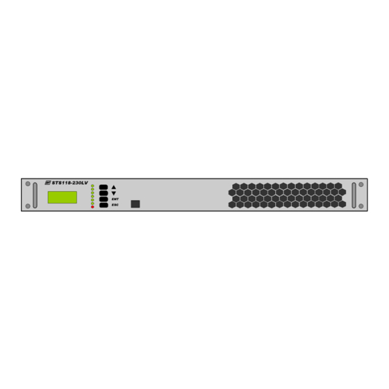
Page 9 (24) 3.2 Necessary equipment for STS118 assembly: Assembly set 19” sub rack 1U for one static transfer switch STS118 including a wired back- plane): Material code= 602-118-011.00 3.3 Front view: control elements, indicators Figure 2. Front view... -
Page 10: Electrical Connections
X8 X7 X7 X6 X6 X5 X5 X4 X4 X3 X3 X2 X2 X1 X13 X12 X12 X11 Figure 3. Backplane, shown from the rear side Figure 4. Detail X10 & X15 (synchronous bus connectors) ©2009. ELTEK VALERE DEUTSCHLAND GmbH. UM_STS118_E_R0.0... -
Page 11: Pin Assignment Of The Rear Side Backplane Connectors
2,5/2-G supply 0.75mm DC minus (-) 0.75mm DC plus (+) STS118HV: Vi = 91.8-275V ; STS118LV: Vi = 38-75V ; STS118-24V: Vi = 19-45V X22 & Two CAN-Bus con- RJ11, 6-pole Cord Set nectors ©2009. ELTEK VALERE DEUTSCHLAND GmbH. UM_STS118_E_R0.0... -
Page 12: Pin Assignment Of The Rear Side Can-Bus Connectors X22 & X23 (Rj11)
3.4.3 Pin assignment of the front side Ethernet connector (RJ45): Name Designation Tranceive Data + Tranceive Data - Receive Data + Not used Not used Receive Data - Not used Not used Figure 6. Front side Ethernet connector (socket outlet RJ45, 8-pole) ©2009. ELTEK VALERE DEUTSCHLAND GmbH. UM_STS118_E_R0.0... -
Page 13: Cooling/Air Flow Direction
3.6 Communication interfaces 3.6.1 CAN-Bus The STS118 is equipped with a serial data interface in accordance with the Controller Area Network (CAN) specification. The CAN-Bus connection is integrated in the rear side of the STS module. Via CAN-Bus the communication of the STS118 with the connected inverters and a possibly implemented UPC3 DC controller unit takes place. -
Page 14: Ethernet (Net Connection)
Page 14 (24) 3.6.2 Ethernet (Net Connection) Furthermore the STS118 is fitted with a front side Ethernet interface (10/100MB) for remote control via HTTP (WEB server), SNMP, SMTP und SNTP. The STS can be directly configured via PC. Furthermore, extensive remote control can be realized. -
Page 15: Handling
STS corresponds to the specification as specified on the type plate. 1. Carefully unpack the unit 2. Put the unit into the provided slot of the STS118 sub rack. 3. Carefully slide in the unit until the module connector touched the backplane connector. -
Page 16: Led Indications
during menu item selection: change to next item (parameter) during adjustment mode: decrease value enter menu (long pressed) enter submenu save parameter and leave submenu leave the menu without changing enter error list ©2009. ELTEK VALERE DEUTSCHLAND GmbH. UM_STS118_E_R0.0... -
Page 17: Lc-Display: Indication Of Measured Values And Alarm Messages
(see section 5.1) are switched “active” and therefore they are visible on the display in case of failure. The alarm messages which shall not be visible on the display in case of failure are to be switched “inactive” in the customer menu (see the diagram “customer menu”). ©2009. ELTEK VALERE DEUTSCHLAND GmbH. UM_STS118_E_R0.0... -
Page 18: Parameter Adjustment / Menu Structure
Battery voltage low DC-voltage high Battery voltage high fan error Internal fan error Uout error Output voltage < 95% Vin (Mains/INV) Ubatt< warning Battery voltage < warning level Ubatt> warning Battery voltage > warning level ©2009. ELTEK VALERE DEUTSCHLAND GmbH. UM_STS118_E_R0.0... -
Page 19: Structure Of The Customer Menu
The customer menu can be entered from the Basic display by pressing “ENT” for approx. three seconds and then press “ENT” again. For a list of all selectable individual alarm messages for the collective failure (CF) signalization, see section 5.1 Figure 10. Structure of the customer menu ©2009. ELTEK VALERE DEUTSCHLAND GmbH. UM_STS118_E_R0.0... -
Page 20: Figure 11. Continuation Of The Customer Menu
Static transfer switch STS118 User Manual Page 20 (24) Figure 11. Continuation of the customer menu The final display shows the currently used Firmware version. ©2009. ELTEK VALERE DEUTSCHLAND GmbH. UM_STS118_E_R0.0... -
Page 21: Maintenance
The display “Alarm Messages” can be quit by pressing “ESC” again. Basic display Figure 12. Display “Alarm Messages” In the table on the following page all possible alarm messages are listed and described. ©2009. ELTEK VALERE DEUTSCHLAND GmbH. UM_STS118_E_R0.0... - Page 22 ##Example: The INV rack is running with three INVs (each 2.25kVA) from which one is configured as redundant. If the STS output power exceeds 4.5kVA the error “INV red. overl.” will occur. The system output power is too high for the two not redundant INVs! ©2009. ELTEK VALERE DEUTSCHLAND GmbH. UM_STS118_E_R0.0...
-
Page 23: Technical Specifications
Type of construction 19“, 1U Dimensions (W/H/D) 483/44.4/335mm (preliminary data) Minimum installation depth 400mm with dedicated sub rack Weight Colour Front panel: RAL 7035, print: neutral jet black, RAL 9005 ©2009. ELTEK VALERE DEUTSCHLAND GmbH. UM_STS118_E_R0.0... -
Page 24: Dimensional Drawings
Compliance to EMC standards EN61000-6-5 (Immunity for Power Station and MV Substation Environments) Rear side: AC inputs/output, DC input and signalization Electrical connections Front side: Ethernet (RJ45) 8.1 Dimensional drawings Figure 13. Module dimensions ©2009. ELTEK VALERE DEUTSCHLAND GmbH. UM_STS118_E_R0.0...
Need help?
Do you have a question about the STS118 and is the answer not in the manual?
Questions and answers