Table of Contents
Advertisement
Quick Links
Advertisement
Table of Contents

Subscribe to Our Youtube Channel
Summary of Contents for Mechatronics eurosens DSS
- Page 1 v 1.01 LOAD CONTROLLER eurosens User manual...
- Page 2 1.01 eurosens DSS USER MANUAL...
-
Page 3: Table Of Contents
General information Specification of eurosens DSS Installation of eurosens DSS 3.1 Choosing installation place 3.2 Installation recommendations Connection of eurosens DSS Settings and calibration of eurosens DSS 5.1 Connection procedure 5.2 Calibration of sensor 5.2.1 Sensor reset 5.2.2 Sensor calibration on server side 5.2.3... - Page 4 1.01 eurosens DSS USER MANUAL ERMS AND DEFINITIONS eurosens Load controller/axle load sensor/sensor – DSS. Calibration – changing of sensor settings. PC – personal computer. Vehicle – a truck, tractor, bus, locomotive, river boat, diesel genset, stationary tank, boiler/burner.
-
Page 5: General Information
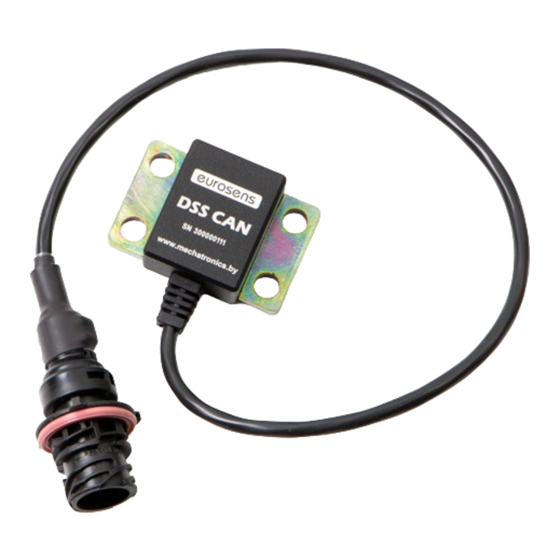
DSS USER MANUAL ENERAL INFORMATION _____________________________________________________________________________________ Load controller (axle load sensor) eurosens DSS (fig. 1.1) is used to determine the axle load of a vehicle by measuring the microdeformations of the load-bearing elements, such as an axle or suspension arms. -
Page 6: Specification Of Eurosens Dss
IP 67 Dimensions, mm 65x45x26 Measurement error of eurosens DSS depends on the microstrain of the element the sensor is fixed on. The more the load-bearing element is deformed under load, the more sensitive the sensor is to axle load... -
Page 7: Installation Of Eurosens Dss
1.01 eurosens DSS USER MANUAL eurosens DSS NSTALLATION OF _____________________________________________________________________________________ 3.1 C HOOSING INSTALLATION PLACE When choosing an installation place, consider the required dimensions of the mounting pads and the axle deformation zones shown in fig. 3.1 fig. 3.2. - Page 8 1.01 eurosens DSS USER MANUAL • It is possible to install one sensor eurosens DSS in the center of the non- driving (front) axle (fig. 3.3), or two sensors – each on the left and right side of the axle (fig.
- Page 9 When installing on the rear axle, the preferred installation location is the section between the leaf spring mount and the wheel. In this case two sensors eurosens DSS must be installed – each on the left and right side of a vehicle (fig.
-
Page 10: Installation Recommendations
1.01 eurosens DSS USER MANUAL 3.2 I NSTALLATION RECOMMENDATIONS 1) Clean the sensor installation site: degrease, remove excess moisture and all kinds of non-metallic objects, remove rust and other contaminants. 2) Cleaning can be done manually by using metal brushes, files, emery paper, or by using a grinder. - Page 11 1.01 eurosens DSS USER MANUAL 5) Install the sensor on the pins of the supports so that the sensor case is fully adjacent to the supports, and fix it with the screws from the mounting kit (fig. 3.8). screw М8-7g...
-
Page 12: Connection Of Eurosens Dss
1.01 eurosens DSS USER MANUAL eurosens DSS ONNECTION OF _____________________________________________________________________________________ eurosens DSS sensor can be connected using CAN bus interface. Sensor pinout is given in fig. 4.1. 1 – VBAT 2 – GND brown 3 – CANH yellow 4 – CANL green fig. - Page 13 1.01 eurosens DSS USER MANUAL • Use eurosens Display CAN to display axle loads and cargo weight to a driver (fig. 4.3). fig. 4.3. eurosens Display with eurosens DSS sensor...
-
Page 14: Settings And Calibration Of Eurosens Dss
Destination CAN. 5.1 C ONNECTION PROCEDURE 1) Download the service software eurosens DSS CAN Configurator from the eurosens DSS CAN product page and install it on your PC. 2) Connect the service adapter eurosens Destination to your PC via a USB port. - Page 15 1.01 eurosens DSS USER MANUAL fig. 5.2. Information about connected sensor...
-
Page 16: Calibration Of Sensor
1.01 eurosens DSS USER MANUAL 5.2 C ALIBRATION OF SENSOR 5.2.1 S ENSOR RESET Sensor calibration allows you to set the calculation table for conversion of the primary sensor values (detector values) into the output values of the sensor. - Page 17 1.01 eurosens DSS USER MANUAL • After reset procedure the initial detector value is set to 10000 and default sensor calibration table looks as shown in fig. 5.4. • Default calibration is linear (scaled 1:1). The output value of the sensor is equal to the internal detector value.
-
Page 18: Sensor Calibration On Server Side
1.01 eurosens DSS USER MANUAL 5.2.2 S ENSOR CALIBRATION ON SERVER SIDE With the "default" calibration stored in the sensor, the conversion of the detector value into kilograms must be carried out on the server side. • To create calibration table at server side there is no need to visit a vehicle and measure real axle loads with direct connection to sensors. - Page 19 1.01 eurosens DSS USER MANUAL • add a new line to the calibration table by pressing the button "Calibrate"; • make at least 2 records for an empty and fully loaded vehicle. It is possible to fill in the calibration table in several steps by saving intermediate calibration values to the sensor.
-
Page 20: Support Of Several Calibration Tables
1.01 eurosens DSS USER MANUAL 5.2.4 S UPPORT OF SEVERAL CALIBRATION TABLES One sensor can store up to 3 independent calibration tables (fig. 5.5). It allows you to use one sensor as a source of 3 independent axle loads. This feature is helpful when a vehicle has several closely spaced axles. -
Page 21: Sensor Settings
1.01 eurosens DSS USER MANUAL 5.4 S ENSOR SETTINGS The tab “Settings” contains the settings for the sensor interface and data processing (fig. 5.7): • Averaging defines averaging interval for output data, is measured in seconds. • Detector/Filtering defines the threshold for data filtering, is measured in seconds. - Page 22 29-bit CAN bus message identifier. Data field is described in Table 2. SA field defines the sensor address in the CAN bus network Table 2. Structure of the eurosens DSS data field Bytes Internal detector value, 4 bytes, unsigned...
-
Page 23: Additional Information
1.01 eurosens DSS USER MANUAL DDITIONAL INFORMATION _____________________________________________________________________________________ 6.1 S TORAGE eurosens It is recommended to store DSS in dry enclosed areas. eurosens DSS may only be stored in its original packaging at temperature range from -50 to + 40 °С and relative humidity up to 100% at +25 ° С. -
Page 24: Technical Support
1.01 eurosens DSS USER MANUAL 6.4 T ECHNICAL SUPPORT +37525-691-87-76 +37525-691-87-76 support@mechatronics.by 6.5 C ONTACTS JSC Mechatronics 80/3 1 May Street Vileyka, 222416 Belarus t: +375 (1771) 33011 f: +375 (1771) 24190 E-mail: office@mechatronics.by www.mechatronics.by/en... -
Page 25: Appendix 1. Dimensions Of Eurosens Dss
1.01 eurosens DSS USER MANUAL eurosens DSS 1. D PPENDIX IMENSIONS OF... - Page 26 JSC Mechatronics 80/3 1 May Street, Vileyka, Belarus, t: +375 (1771) 33011, f: +375 (1771) 24190 E-mail: office@mechatronics.by www.mechatronics.by/en...
Need help?
Do you have a question about the eurosens DSS and is the answer not in the manual?
Questions and answers