Table of Contents
Advertisement
Quick Links
Model Sounds™
Mono Amplifier Kit – MSMAK66
Build yourself an amplifier kit that can be permanently located
on your layout.
Locate it in a building or a fixed vehicle or any awkward space
enhancing your layout
Just solder the jack lead, speaker & USB lead to the board and
you are good to go
Kit Requires
USB power supply 5.5V 1A mains plug (supplied separately)
•
or
2x AA batteries & clip (supplied separately)
•
Tools Required
Soldering iron
•
Solder
•
Wire cutters
•
Wire strippers
•
Model Sounds™
Email; gavin@stoneybridge.co.uk
Tel; 07970 883663
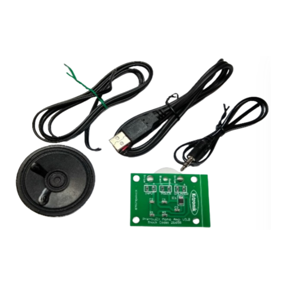
Kit Contents
(Pic 1 left to right, top to
bottom)
• 1m Speaker cable
• 1m USB power cable
• 0.5m 3.5mm Jack cable
• 66mm 8Ω 0.5W speaker
• 2165B Amplifier board
Website; www.model-sounds.co.uk
Build Instructions
Before you start, familiarise yourself with the printed circuit board (PCB).
We use a KITRONIK pre-built board with the only soldering required is the
connections of the various leads.
The kit is provided with three cables which need to be attached to the PCB. Each
connection needs to go through the strain relief holes (Pic 2) as shown in the
picture and soldered on the reverse (Pic 3).
Pic 2
Pic 3
Connect the wires
Start with the connection labelled 'speaker'. The kit is supplied with a 1m length
of speaker cable. This will be used to connect the PCB to the speaker and can be
trimmed to suit.
Strip off the insulation on each end of the cable. Connect one end to the two
terminals on the speaker (Pic 4) and the other end to the board marked
'speaker'.
The cable has a stripe printed on it denoting the negative core (-). The speaker is
not polarity sensitive but you may wish to connect the stripe to the pad on the
board marked stripe or '-'
*
The middle connection is for the power. The USB cable provided with the kit
should be connected to the PCB. The red wire connects to terminal marked
'Red' or '+' and the black wire to the terminal marked '-'
*
The final connection is the audio input. Strip the insulation off the other end of
the cable that has the audio jack plug on. Solder these wires into the PCB where
it is labelled input. Connect the wire with the stripe to the pad on the board
marked stripe or '-' and the remaining wire to the terminal marked '+'
* Please note! The power and inputs are polarity sensitive and your amplifier will
not work if the terminals are crossed.
Pic4
Advertisement
Table of Contents

Related Manuals for MODEL SOUNDS MSMAK66

Summary of Contents for MODEL SOUNDS MSMAK66
- Page 1 We use a KITRONIK pre-built board with the only soldering required is the connections of the various leads. Mono Amplifier Kit – MSMAK66 The kit is provided with three cables which need to be attached to the PCB. Each connection needs to go through the strain relief holes (Pic 2) as shown in the Build yourself an amplifier kit that can be permanently located picture and soldered on the reverse (Pic 3).
- Page 2 How to get the cables to the correct places • Porting to give the best audio sound • The PCB should ideally be mounted on stand-off bolts using the four corner holes. Bolts of 3mm are suggested. Model Sounds™ Email; gavin@stoneybridge.co.uk Website; www.model-sounds.co.uk Tel; 07970 883663...
Need help?
Do you have a question about the MSMAK66 and is the answer not in the manual?
Questions and answers